- 您现在的位置:买卖IC网 > PDF目录15895 > IRDCIP2001-A (International Rectifier)IC CONVRTR 2PH BUCK 40A W/IP2001 PDF资料下载
参数资料
| 型号: | IRDCIP2001-A |
| 厂商: | International Rectifier |
| 文件页数: | 4/10页 |
| 文件大小: | 0K |
| 描述: | IC CONVRTR 2PH BUCK 40A W/IP2001 |
| 标准包装: | 1 |
| 系列: | iPOWIR™ |
| 主要目的: | DC/DC,步降 |
| 输出及类型: | 1,非隔离 |
| 功率 - 输出: | 68W |
| 输出电压: | 1.7V |
| 电流 - 输出: | 40A |
| 输入电压: | 5 ~ 12 V |
| 稳压器拓扑结构: | 降压 |
| 频率 - 开关: | 500kHz |
| 板类型: | 完全填充 |
| 已供物品: | 板 |
| 已用 IC / 零件: | iP2001 |
| 其它名称: | *IRDCIP2001-A |
�� �
�
�iP2001�
�5.0�
�4.5�
�22�
�20�
�4.0�
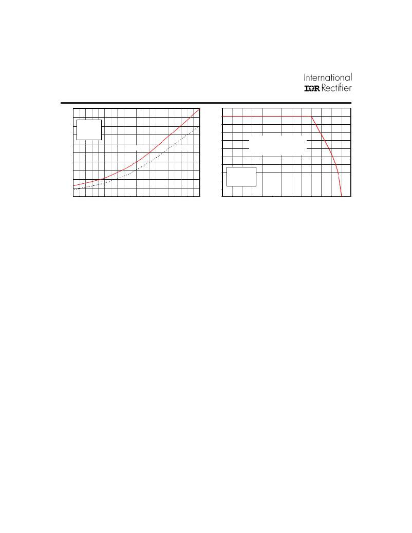
�V� IN� =� 12V�
�V� OUT� =� 1.6V�
�T� BLK� =� 125°C�
�18�
�16�
�3.5�
�3.0�
�f� SW� =� 500kHz�
�14�
�Safe� Operating�
�2.5�
�Maximum�
�Typical�
�12�
�Area�
�10�
�2.0�
�8�
�1.5�
�1.0�
�0.5�
�0.0�
�6�
�4�
�2�
�0�
�V� IN� =� 12V�
�V� OUT� =� 1.6V�
�f� SW� =� 500kHz�
�0�
�1�
�2�
�3�
�4�
�5�
�6�
�7�
�8�
�9�
�10�
�11�
�12�
�13�
�14�
�15�
�16�
�17�
�18�
�19�
�20�
�0�
�10�
�20�
�30�
�40�
�50�
�60�
�70�
�80�
�90�
�100�
�110�
�120�
�130�
�Fig� 2.� Safe� Operating� Area� (SOA)� vs.� T� PCB� *�
�Output� Current� (A)�
�Fig� 1.� Power� Loss� vs.� Current�
�PCB� Temperature� (oC)�
�(� *� see� AN-1030� for� details)�
�Adjusting� the� Power� Loss� and� SOA� curves� for� different� operating� conditions�
�To� make� adjustments� to� the� power� loss� curves� in� Fig.� 1,� multiply� the� normalized� value� obtained� from� the� curves� in� Figs.� 3,�
�4,� 5� or� 6� by� the� value� indicated� on� the� power� loss� curve� in� Fig.� 1.� If� multiple� adjustments� are� required,� multiply� all� of� the�
�normalized� values� together,� then� multiply� that� product� by� the� value� indicated� on� the� power� loss� curve� in� Fig.� 1.� The� resulting�
�product� is� the� final� power� loss� based� on� all� factors.�
�To� make� adjustments� to� the� SOA� curve� in� Fig.� 2,� determine� the� maximum� allowed� PCB� temperature� in� Fig.� 2� at� the� required�
�operating� current.� Then,� add� the� correction� temperature� from� the� normalized� curves� in� Figs.� 3,� 4,� 5� or� 6� to� find� the� final�
�maximum� allowable� PCB� temperature.� When� multiple� adjustments� are� required,� add� all� of� the� temperatures� together,� then�
�add� the� sum� to� the� PCB� temperature� indicated� on� the� SOA� graph� to� determine� the� final� maximum� allowable� PCB� temperature�
�based� on� all� factors.�
�Operating� Conditions� for� the� examples� below:�
�Output� Current� =� 20A�
�Output� Voltage� =� 2.5V�
�Adjusting� for� Maximum� Power� Loss:�
�Input� Voltage� =� 7V�
�Sw� Freq=� 750kHz�
�(Fig.� 1)�
�(Fig.� 3)�
�(Fig.� 4)�
�(Fig.� 5)�
�Maximum� power� loss� =� 5W�
�Normalized� power� loss� for� input� voltage� ≈� 0.925�
�Normalized� power� loss� for� output� voltage� ≈� 1.1�
�Normalized� power� loss� for� frequency� ≈� 1.225�
�Adjusted� Power� Loss� =� 5W� x� 1.1� x� 0.925� x� 1.225� ≈� 6.23W�
�Adjusting� for� SOA� Temperature:�
�4�
�(Fig.� 2)�
�(Fig.� 3)�
�(Fig.� 4)�
�(Fig.� 5)�
�SOA� PCB� Temperature� =� 90°C�
�Normalized� SOA� PCB� Temperature� for� input� voltage� ≈� 2.6°C�
�Normalized� SOA� PCB� Temperature� for� output� voltage� ≈� -3.5°C�
�Normalized� SOA� PCB� Temperature� for� frequency� ≈� -7.5°C�
�Adjusted� SOA� PCB� Temperature� =� 90°C� -� 3.5°C� +� 2.6°C� -� 7.5°� ≈� 81.6°C�
�www.irf.com�
�相关PDF资料 |
PDF描述 |
|---|---|
| RP20-1215SF-HC | CONV DC/DC 20W 9-18VIN 15VOUT |
| MAX6431AHUS+T | IC MONITOR BAT LP SOT143-4 |
| RSA06DTBI | CONN EDGECARD 12POS R/A .125 SLD |
| EEC65DRTI-S13 | CONN EDGECARD 130POS .100 EXTEND |
| 2249-K-180 | CABLE BNC MALE RG174/U 15FT |
相关代理商/技术参数 |
参数描述 |
|---|---|
| IRDCIP2001-B | 功能描述:IC CONVRTR 3PH BUCK 60A W/IP2001 RoHS:否 类别:编程器,开发系统 >> 过时/停产零件编号 系列:iPOWIR™ 标准包装:1 系列:- 类型:MCU 适用于相关产品:Freescale MC68HC908LJ/LK(80-QFP ZIF 插口) 所含物品:面板、缆线、软件、数据表和用户手册 其它名称:520-1035 |
| IRDCIP2001-C | 功能描述:IC CONVRTR 4PH BUCK 80A W/IP2001 RoHS:否 类别:编程器,开发系统 >> 过时/停产零件编号 系列:iPOWIR™ 标准包装:1 系列:- 类型:MCU 适用于相关产品:Freescale MC68HC908LJ/LK(80-QFP ZIF 插口) 所含物品:面板、缆线、软件、数据表和用户手册 其它名称:520-1035 |
| IRDCIP2002-C | 制造商:International Rectifier 功能描述:Evaluation Kit For 1MHz, 120A, 4-Phase Synchronous Buck Converter Using IP2002 制造商:International Rectifier 功能描述:REFERENCE DESIGN KIT 制造商:IR 功能描述:Reference Design Kit for the iP2002 1MHz 120A 4-Phase Synchronous Buck Converter |
| IRDCIP2003A-C | 功能描述:KIT DESIGN 4PH 160A 1MHZ IP2003A RoHS:是 类别:编程器,开发系统 >> 过时/停产零件编号 系列:- 标准包装:1 系列:- 类型:MCU 适用于相关产品:Freescale MC68HC908LJ/LK(80-QFP ZIF 插口) 所含物品:面板、缆线、软件、数据表和用户手册 其它名称:520-1035 |
| IRDCIP2005A-A | 功能描述:电源管理IC开发工具 1MHZ 65A DC 80A PEAK DUAL PHASE SYNC RoHS:否 制造商:Maxim Integrated 产品:Evaluation Kits 类型:Battery Management 工具用于评估:MAX17710GB 输入电压: 输出电压:1.8 V |
发布紧急采购,3分钟左右您将得到回复。