- 您现在的位置:买卖IC网 > PDF目录261363 > IRKL162-16D25 (VISHAY SEMICONDUCTORS) 355 A, 1600 V, SCR PDF资料下载
参数资料
| 型号: | IRKL162-16D25 |
| 厂商: | VISHAY SEMICONDUCTORS |
| 元件分类: | 晶闸管 |
| 英文描述: | 355 A, 1600 V, SCR |
| 文件页数: | 6/13页 |
| 文件大小: | 251K |
| 代理商: | IRKL162-16D25 |
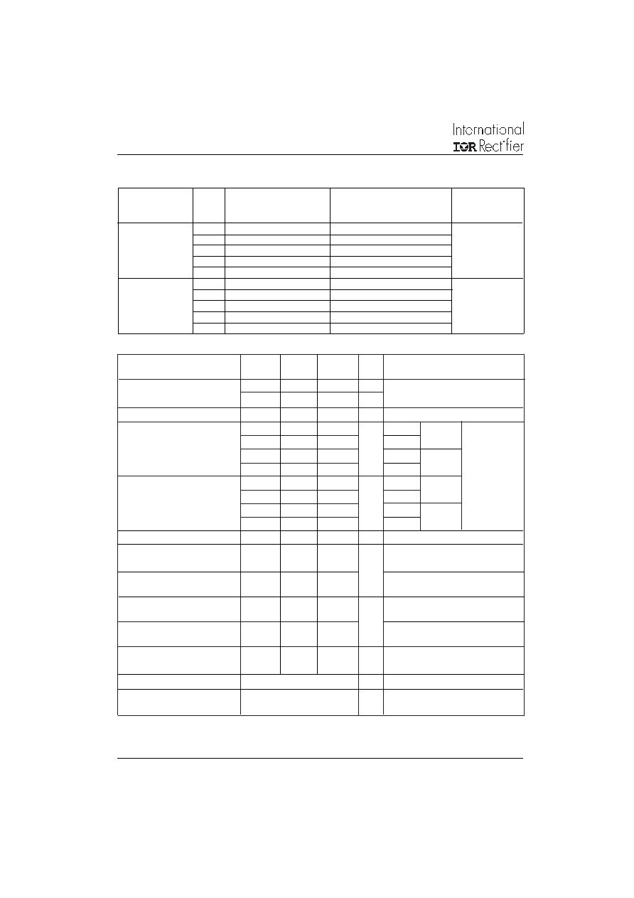
IRK.135, .136, .141, .142, .161, .162 Series
2
Bulletin I27101 rev. A 09/97
www.irf.com
I
T(AV)
Max. average on-state current
135
140
160
A
180° conduction, half sine wave
@ Case temperature
85
°C
I
T(RMS) Max. RMS on-state current
300
310
355
A
as AC switch
I
TSM
Maximum peak, one-cycle
3200
4750
5100
A
t = 10ms
No voltage
on-state, non-repetitive
3360
5000
5350
t = 8.3ms reapplied
surge current
2700
4000
4300
t = 10ms
100% V
RRM
2800
4200
4500
t = 8.3ms reapplied
Sine half wave,
I2t
Maximum I2t for fusing
51.5
113
131
KA2s
t = 10ms
No voltage
Initial T
J
= T
J
max.
47
103
119
t = 8.3ms reapplied
36
80
92
t = 10ms
100% V
RRM
33
73
84
t = 8.3ms reapplied
I2
√t
Maximum I2
√t for fusing
515
1130
1310
KA2
√s t = 0.1 to 10ms, no voltage reapplied
V
T(TO)1
Low level value of threshold
0.98
0.75
0.79
V
(16.7% x
π x I
T(AV)
< I <
π x I
T(AV)
), @ T
J
max.
voltage
V
T(TO)2
High level value of threshold
101
0.86
0.92
(I >
π x I
T(AV)
), @ T
J
max.
voltage
rt1
Low level value on-state
1.62
0.92
0.64
m
(16.7% x
π x I
T(AV)
< I <
π x I
T(AV)
), @ T
J
max.
slope resistance
rt2
High level value on-state
1.56
0.77
0.49
(I >
π x I
T(AV)
), @ T
J
max.
slope resistance
V
FM
Maximum forward voltage drop
1.66
1.32
1.26
V
I
FM
=
π x I
F(AV)
, T
J
= max., 180°conduction
Av. power = V
F(TO) x IF(AV) + rf
x (I
F(RMS))
2
I
H
Maximum holding current
500
mA
Anode supply = 12V initial I
T = 30A, TJ = 25°C
I
L
Maximum latching current
300
mA
Anode supply = 12V resistive load = 1
gate
pulse: 10V, 100s, T
J = 25°C
Parameter
Units Conditions
IRK.135.
IRK.141.
IRK.161.
IRK.136.
IRK.142.
IRK.162.
Forward Conduction
ELECTRICAL SPECIFICATIONS
Voltage Ratings
Type number
Voltage
VRRM, maximum repetitive
VRSM, maximum non-repetitive
IRRM max.
Code
peak reverse voltage
@ 150°C
VV
mA
IRK.135, IRK.136
04
400
500
50
IRK.161, IRK.162
08
800
900
12
1200
1300
14
1400
1500
16
1600
1700
IRK.141, IRK.142
08
800
900
50
12
1200
1300
16
1600
1700
18
1800
1900
20
2000
2100
相关PDF资料 |
PDF描述 |
|---|---|
| IRKL26/12S90 | 60 A, 1200 V, SCR, TO-240AA |
| IRKL26/14S90 | 60 A, 1400 V, SCR, TO-240AA |
| IRKL26/16S90 | 60 A, 1600 V, SCR, TO-240AA |
| IRKH26/16A | 42.39 A, 1600 V, SCR, TO-240AA |
| IRKH161-14 | 355 A, 1400 V, SCR |
相关代理商/技术参数 |
参数描述 |
|---|---|
| IRKL162-16D25N | 制造商:未知厂家 制造商全称:未知厂家 功能描述:THYRISTOR MODULE|DOUBLER|HALF-CNTLD|NEGATIVE|2.5KV V(RRM)|160A I(T) |
| IRKL166/16 | 制造商:n/a 功能描述:_ |
| IRKL170-04 | 制造商:未知厂家 制造商全称:未知厂家 功能描述:400V 170A Doubler Circuit Positive Phase Control Thyristor/Diode in a MAGN-A-Pak package |
| IRKL170-04D20 | 制造商:未知厂家 制造商全称:未知厂家 功能描述:THYRISTOR MODULE|DOUBLER|HALF-CNTLD|NEGATIVE|400V V(RRM)|170A I(T) |
| IRKL170-04D20N | 制造商:未知厂家 制造商全称:未知厂家 功能描述:THYRISTOR MODULE|DOUBLER|HALF-CNTLD|NEGATIVE|400V V(RRM)|170A I(T) |
发布紧急采购,3分钟左右您将得到回复。