- 您现在的位置:买卖IC网 > Datasheet目录985 > IRPLLED1 (International Rectifier)BOARD EVALUATION FOR IRS2540PBF Datasheet资料下载
参数资料
| 型号: | IRPLLED1 |
| 厂商: | International Rectifier |
| 文件页数: | 8/15页 |
| 文件大小: | 0K |
| 描述: | BOARD EVALUATION FOR IRS2540PBF |
| 标准包装: | 1 |
| 电流 - 输出 / 通道: | 1.5A |
| 输出及类型: | 1,非隔离 |
| 输出电压: | 24V |
| 特点: | 可调光 |
| 输入电压: | 50 ~ 170V |
| 已供物品: | 板 |
| 已用 IC / 零件: | IRS2540PBF |
| 相关产品: | IRS2540PBF-ND - IC LED DRVR HP CONST CURR 8-DIP |
�� �
�
�IRS254(0,1)(S)PbF�
�HO�
�LO�
�Watchdog� Timer�
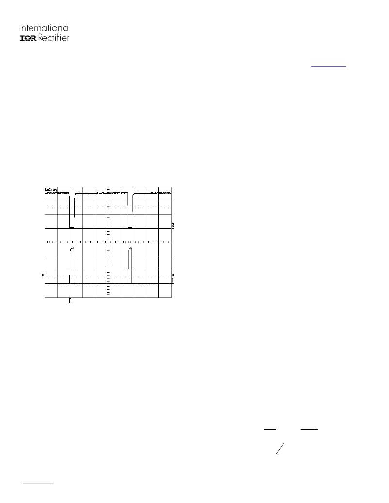
�During� an� open� circuit� condition,� without� the�
�watchdog� timer,� the� HO� output� would� remain� high� at�
�all� times� and� the� charge� stored� in� the� bootstrap�
�capacitor� C� BOOT� would� gradually� discharge� the�
�floating� power� supply� for� the� high-side� driver,� which�
�would� then� be� unable� to� fully� switch� on� the� upper�
�MOSFET� causing� high� losses.� To� maintain�
�sufficient� charge� on� the� bootstrap� capacitor,� a�
�watchdog� timer� has� been� implemented.� In� the�
�condition� where� V� IFB� remains� below� V� IFBTH� ,� the� HO�
�output� will� be� forced� low� after� 20� μ� s� and� the� LO�
�output� forced� high.� This� toggling� of� the� outputs� will�
�last� for� approximately� 1� μ� s� to� maintain� and� replenish�
�sufficient� charge� on� C� BOOT� .�
�Fig.4� Illustration� of� Watchdog� Timer�
�Bootstrap� Capacitor� and� Diode�
�The� bootstrap� capacitor� value� needs� to� be� chosen�
�so� that� it� maintains� sufficient� charge� for� at� least� the�
�approximately� 20� μ� s� interval� until� the� watchdog� timer�
�allows� the� capacitor� to� recharge.� If� the� capacitor�
�value� is� too� small,� the� charge� will� dissipate� in� less�
�than� 20� μ� s.� The� typical� bootstrap� capacitor� is�
�approximately� 100� nF.�
�The� bootstrap� diode� should� be� a� fast� recovery� or�
�ultrafast� recovery� component� to� maintain� good�
�Design� Tip� (DT� 98-2),� “Bootstrap� Component�
�Selection� For� Control� ICs”� at� www.irf.com� under�
�Design� Support�
�Disable� (ENN)� Pin�
�The� disable� pin� can� be� used� for� dimming� and� open-�
�circuit� protection.� When� the� ENN� pin� is� held� low,� the�
�chip� remains� in� a� fully� functional� state� with� no�
�alterations� to� the� operating� environment.� To� disable�
�the� control� feedback� and� regulation,� a� voltage�
�greater� than� V� ENTH� (approximately� 2.5� V)� needs� to� be�
�applied� to� the� ENN� pin.� With� the� chip� in� a� disabled�
�state,� HO� output� will� remain� low,� whereas� the� LO�
�output� will� remain� high� to� prevent� V� S� from� floating,� in�
�addition� to� maintaining� charge� on� the� bootstrap�
�capacitor.� The� threshold� for� disabling� the�
�IRS254(0,1)� has� been� set� to� 2.5� V� to� enhance�
�immunity� to� any� externally� generated� noise,� or�
�application� ground� noise.� This� 2.5� V� threshold� also�
�makes� it� ideal� to� receive� a� drive� signal� from� a� local�
�microcontroller.�
�Dimming� Mode�
�To� achieve� dimming,� a� signal� with� constant�
�frequency� and� set� duty� cycle� can� be� fed� into� the�
�ENN� pin.� There� is� a� direct� linear� relationship�
�between� the� average� load� current� and� duty� cycle.� If�
�the� ratio� is� 50%,� 50%� of� the� maximum� set� light�
�output� will� be� realized.� Likewise� if� the� ratio� is� 30%,�
�70%� of� the� maximum� set� light� output� will� be� realized.�
�A� sufficiently� high� frequency� of� the� dimming� signal�
�must� be� chosen� to� avoid� flashing� or� “strobe� light”�
�effect.� A� signal� on� the� order� of� a� few� kHz� should� be�
�sufficient.�
�The� minimum� amount� of� dimming� achievable� (light�
�output� approaches� 0%)� will� be� determined� by� the�
�“on”� time� of� the� HO� output,� when� in� a� fully� functional�
�regulating� state.� To� maintain� reliable� dimming,� it� is�
�recommended� to� keep� the� “off”� time� of� the� enable�
�signal� at� least� 10� times� that� of� the� HO� “on”� time.� For�
�example,� if� the� application� is� running� at� 75� kHz� with�
�an� input� voltage� of� 100� V� and� an� output� voltage� of�
�20� V,� the� HO� “on”� time� will� be� 3.3� μs� (one-fourth� of�
�the� period� –� see� calculations� below)� according� to�
�standard� buck� topology� theory.� This� will� set� the�
�minimum� “off”� time� of� the� enable� signal� to� 33� μs.�
�efficiency.� Since� the� cathode� of� the� bootstrap� diode�
�will� be� switching� between� zero� and� to� the� high�
�voltage� bus,� the� reverse� recovery� time� of� this� diode�
�Duty� Cycle� =�
�V� out�
�V� in�
�?� 100� =�
�20� V�
�100� V�
�*� 100� =� 20� %�
�is� of� critical� importance.� For� additional� information�
�concerning� the� bootstrap� components,� refer� to� the�
�www.irf.com�
�HO� on� time� =� 20� %� *� 1�
�75� kHz�
�=� 3� .� 3� μ� s�
�Page� 8�
�相关PDF资料 |
PDF描述 |
|---|---|
| ISDCB824 | CABLE RIBBON 24" |
| ISL29000IROZ-EVALZ | EVALUATION BOARD FOR ISL29000 |
| ISL29001IROZ-EVALZ | EVALUATION BOARD FOR ISL29001 |
| ISL29002IROZ-EVALZ | EVALUATION BOARD FOR ISL29002 |
| ISL29003IROZ-EVALZ | EVALUATION BOARD FOR ISL29003 |
相关代理商/技术参数 |
参数描述 |
|---|---|
| IRPLLED1A | 功能描述:电源管理IC开发工具 Hi-Vlt DC-DC Buck Cnvr HBLED Cur Cntrl RoHS:否 制造商:Maxim Integrated 产品:Evaluation Kits 类型:Battery Management 工具用于评估:MAX17710GB 输入电压: 输出电压:1.8 V |
| IRPLLED5 | 制造商:International Rectifier 功能描述: |
| IRPLLED7 | 功能描述:IC MOSFET DRIVER RoHS:否 类别:集成电路 (IC) >> PMIC - MOSFET,电桥驱动器 - 外部开关 系列:* 标准包装:95 系列:- 配置:半桥 输入类型:PWM 延迟时间:25ns 电流 - 峰:1.6A 配置数:1 输出数:2 高端电压 - 最大(自引导启动):118V 电源电压:9 V ~ 14 V 工作温度:-40°C ~ 125°C 安装类型:表面贴装 封装/外壳:8-SOIC(0.154",3.90mm 宽) 供应商设备封装:8-SOIC 包装:管件 产品目录页面:1282 (CN2011-ZH PDF) 其它名称:*LM5104M*LM5104M/NOPBLM5104M |
| IRPLLNR1 | 制造商:未知厂家 制造商全称:未知厂家 功能描述: |
| IRPLLNR2E | 功能描述:KIT BALLAST LINEAR INT 230VAC RoHS:否 类别:编程器,开发系统 >> 过时/停产零件编号 系列:- 标准包装:1 系列:- 类型:MCU 适用于相关产品:Freescale MC68HC908LJ/LK(80-QFP ZIF 插口) 所含物品:面板、缆线、软件、数据表和用户手册 其它名称:520-1035 |
发布紧急采购,3分钟左右您将得到回复。