- 您现在的位置:买卖IC网 > PDF目录360971 > IRPT2062 PDF资料下载
参数资料
| 型号: | IRPT2062 |
| 文件页数: | 2/12页 |
| 文件大小: | 126K |
| 代理商: | IRPT2062 |
page 2
IRPT2051
System Description
The IRPT2051C
power conversion function for a 3hp (2.2kW) variable-frequency,
variable-voltage, AC motor controller. The
combines a power assembly IRPT2051A with a Driver-
Plus
Board IRPT2051D. Figure 1 shows the block diagram of the
within an AC motor control system.
The power module contains a 3-phase input bridge rectifier, 3-
phase IGBT and diode, 3-phase IGBT inverter, current sense
shunts, and a thermistor. It is designed for easy mounting to a
heat sink.
The Driver-Plus Board contains DC link capacitors, capacitor
soft charge function using NTC thermistor, surge suppression
MOVs, IGBT gate drivers, DC bus voltage and current feedback
signals, protection circuitry and local power supply. It is de-
signed to mate with a controller board through a single row
header. Terminal blocks are also provided on the Driver-
Plus
Board for all end-user line input, motor output, and brake resis-
tor.
Output power is Pulse-Width Modulated (PWM), 3-phase,
variable-frequency, variable voltage controlled by an externally-
generated user-provided PWM controller for inverter IGBT
switching. The power supply offers the user non-isolated 5V and
15V to power the microcontroller.
The IRPT2051C offers several benefits to the drive manufac-
turer as listed below:
It eliminates component selection, design layout, intercon-
nection, gate drive, local power supply, thermal sensing,
current sensing, and protection.
Gate drive and protection circuits are designed to closely
match the operating characteristics of the power semicon-
ductors. This allows power losses to be minimized and
power rating to be maximized to a greater extent than is
possible by designing with individual components.
It reduces the effort of calculating and evaluating power
semiconductor losses and junction temperature.
It reduces the manufacturer's part inventory and simplifies
assembly.
[
specifications and ratings are given for
system input and output voltage and current, power losses
and heat sink requirements over a range of operating con-
ditions.
system ratings are verified by IR
in final testing.]
provides the complete
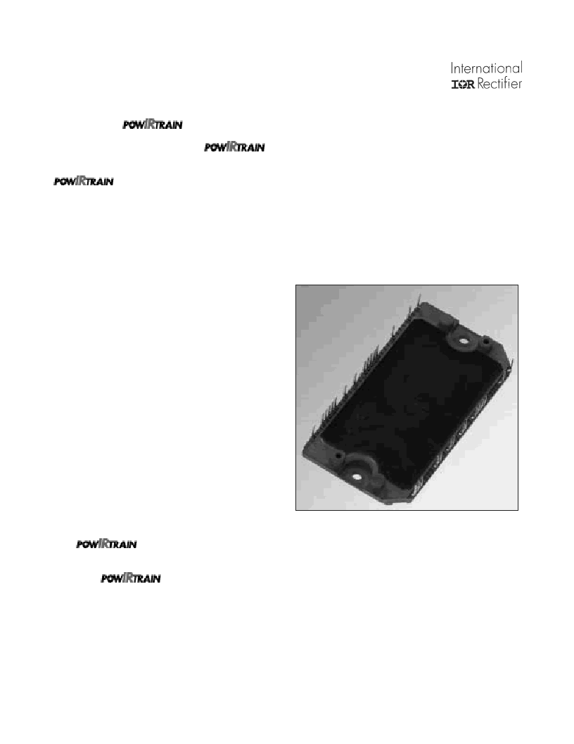
The IRPT2051A Power Module
The IRPT2051A power module, shown in figure 2, is a chip
and wire epoxy-encapsulated module. It houses input rectifiers,
brake IGBT and freewheeling diode, output inverter, current
sense shunts and NTC thermistor. The 3-phase
input bridge
rectifiers
are rated at 1600V. The brake circuit uses 1200V
IGBT and free-wheeling diode. The inverter section employs
1200V,
short circuit rates, ultrafast IGBTs
and
ultrafast free-
wheeling diodes.
Current sensing is achieved through
25 m
low-inductance shunts
provided in the positive and negative
DC bus rail. The
NTC thermistor
provides temperature sensing
capability. The lead spacing on the power modulemeets UL840
pollution level 3 requirements.
Figure 2. IRPT2051A Power Module
The power circuit and layout within the module are carefully
designed to minimize inductance in the power path, to reduce
noise during inverter operation and to improve the inverter effi-
ciency. The Driver-
Plus
Board required to run the inverter can
be soldered to the power module pins, thus minimizing assembly
and alignment. The power module is designed to be mounted to
a heat sink with two screw mount positions, in order to insure
good thermal contact between the module substrate and the heat
sink.
相关PDF资料 |
PDF描述 |
|---|---|
| IRPT2064A | |
| IRPT2051 | Integrated Power Stage for 2.2kW Motor Drives(2.2kW 马达驱动器的集成功率单元) |
| IRPT4052 | |
| IRPT4052 | Integrated Power Stage for 5.5kW Motor Drives(5.5kW 马达驱动器的集成功率单元) |
| IRPT5051 | |
相关代理商/技术参数 |
参数描述 |
|---|---|
| IRPT2062A | 制造商:IRF 制造商全称:International Rectifier 功能描述:Power Module for 3 hp Motor Drives |
| IRPT2064A | 制造商:未知厂家 制造商全称:未知厂家 功能描述: |
| IRPT3054A | 制造商:IRF 制造商全称:International Rectifier 功能描述:Power Module for 5 hp Motor Drives |
| IRPT4052 | 制造商:未知厂家 制造商全称:未知厂家 功能描述: |
| IRPT5051 | 制造商:未知厂家 制造商全称:未知厂家 功能描述: |
发布紧急采购,3分钟左右您将得到回复。