- 您现在的位置:买卖IC网 > PDF目录20829 > IRS25401SPBF (International Rectifier)IC LED CONS CURR CTRL 8SOIC PDF资料下载
参数资料
| 型号: | IRS25401SPBF |
| 厂商: | International Rectifier |
| 文件页数: | 13/20页 |
| 文件大小: | 0K |
| 描述: | IC LED CONS CURR CTRL 8SOIC |
| 标准包装: | 95 |
| 拓扑: | PWM,降压(降压) |
| 输出数: | 1 |
| 内部驱动器: | 无 |
| 类型 - 主要: | 通用 |
| 频率: | 500kHz |
| 安装类型: | 表面贴装 |
| 封装/外壳: | 8-SOIC(0.154",3.90mm 宽) |
| 供应商设备封装: | 8-SOIC |
| 包装: | 管件 |
�� �
�
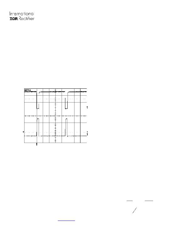
�IRS254(0,1)(S)PbF�
�Watchdog� Timer�
�Disable� (ENN)� Pin�
�During� an� open� circuit� condition,� without� the� watchdog�
�HO�
�LO�
�timer,� the� HO� output� would� remain� high� at� all� times� and�
�the� charge� stored� in� the� bootstrap� capacitor� C� BOOT�
�would� gradually� discharge� the� floating� power� supply� for�
�the� high-side� driver,� which� would� then� be� unable� to� fully�
�switch� on� the� upper� MOSFET� causing� high� losses.� To�
�maintain� sufficient� charge� on� the� bootstrap� capacitor,� a�
�watchdog� timer� has� been� implemented.� In� the�
�condition� where� V� IFB� remains� below� V� IFBTH� ,� the� HO�
�output� is� driven� low� after� 20� μ� s� and� the� LO� output�
�forced� high.� This� toggling� of� the� outputs� will� last� for�
�approximately� 1� μ� s� to� maintain� and� replenish� sufficient�
�charge� on� C� BOOT� .�
�Fig.4� Illustration� of� Watchdog� Timer�
�Bootstrap� Capacitor� and� Diode�
�The� bootstrap� capacitor� value� needs� to� be� selected� so�
�that� it� maintains� sufficient� charge� for� at� least� the�
�approximately� 20� μ� s� interval� until� the� watchdog� timer�
�allows� the� capacitor� to� recharge.� If� the� capacitor� value�
�is� too� small,� it� will� discharge� in� less� than� 20� μ� s.� The�
�typical� bootstrap� capacitor� is� approximately� 100� nF.�
�The� bootstrap� diode� must� be� a� fast� recovery� or� ultrafast�
�The� disable� pin� can� be� used� for� PWM� dimming� and�
�open-circuit� protection.� When� the� ENN� pin� is� held�
�low,� the� chip� remains� in� a� fully� functional� state� with� no�
�alterations� to� the� operating� environment.� To� disable�
�the� control� feedback� and� regulation,� a� voltage� greater�
�than� V� ENTH� (approximately� 2.5� V)� needs� to� be� applied�
�to� the� ENN� pin.� With� the� chip� in� a� disabled� state,� HO�
�output� will� remain� low,� whereas� the� LO� output� will�
�remain� high� to� prevent� V� S� from� floating,� in� addition� to�
�maintaining� charge� on� the� bootstrap� capacitor.� The�
�threshold� for� disabling� the� IRS254(01,11)� has� been�
�set� to� 2.5� V� to� enhance� noise� immunity.� This� 2.5� V�
�threshold� also� provides� compatibility� for� a� drive� signal�
�from� a� microcontroller.�
�Dimming� Mode�
�To� achieve� dimming,� a� signal� with� constant� frequency�
�and� adjustable� duty� cycle� can� be� fed� into� the� ENN�
�pin.� There� is� a� direct� linear� relationship� between� the�
�average� load� current� and� duty� cycle.� If� the� ratio� is�
�50%,� 50%� of� the� maximum� set� light� output� will� be�
�realized.� Likewise� if� the� ratio� is� 30%,� 70%� of� the�
�maximum� set� light� output� will� be� realized.� A�
�sufficiently� high� frequency� of� the� dimming� signal� must�
�be� chosen� to� avoid� noticeable� flashing� or� “strobe�
�light”� effect.� A� signal� above� 120Hz� up� to� 5kHz� is�
�sufficient.�
�The� ENN� pin� logic� is� inverted� to� provide� enable� low�
�so� that� the� default� state� is� with� the� IC� running.�
�The� minimum� amount� of� dimming� achievable� (light�
�output� approaches� 0%)� will� be� determined� by� the� “on”�
�time� of� the� HO� output,� when� in� a� fully� functional�
�regulating� state.� To� maintain� reliable� dimming,� it� is�
�recommended� to� keep� the� “off”� time� of� the� enable�
�signal� at� least� 10� times� that� of� the� HO� “on”� time.� For�
�example,� if� the� application� is� running� at� 75� kHz� with�
�an� input� voltage� of� 100� V� and� an� output� voltage� of� 20�
�V,� the� HO� “on”� time� will� be� approximately� 2.7� μs�
�according� to� standard� buck� topology� theory.� This� will�
�set� the� minimum� “off”� time� of� the� enable� signal� to� 27�
�μs.�
�recovery� component� to� maintain� good� efficiency.� Since�
�the� cathode� of� the� bootstrap� diode� will� be� switching�
�between� zero� and� to� the� high� voltage� bus,� the� reverse�
�Duty� Cycle� =�
�V� out�
�V� in�
�?� 100� =�
�20� V�
�100� V�
�*� 100� =� 20� %�
�recovery� time� of� this� diode� is� critical.� For� additional�
�information� concerning� the� bootstrap� components,� refer�
�to� the� Design� Tip� (DT� 98-2),� “Bootstrap� Component�
�HO� on� time� =� 20� %� *� 1�
�75� kHz�
�≈� 2� .� 7� μ� s�
�Selection� For� Control� ICs”� at� www.irf.com� under� Design�
�Support�
�www.irf.com�
�13�
�?� 2010� International� Rectifier�
�相关PDF资料 |
PDF描述 |
|---|---|
| P51-15-S-O-P-4.5OVP-000-000 | SENSOR 15PSI 7/16-20 UNF 2B 4.5V |
| P51-1500-S-H-M12-4.5V-000-000 | SENSOR 1500PSI M12-1.5 6G 4.5V |
| REC3-2415SRWZ/H2/C/SMD | CONV DC/DC 3W 9-36VIN 15VOUT |
| P51-1000-S-AA-I12-4.5V-000-000 | SENSOR 1000PSI 7/16-20 UNF 4.5V |
| P51-3000-S-M-P-4.5OVP-000-000 | SENSOR 3000PSI M10-1.0 6G 4.5V |
相关代理商/技术参数 |
参数描述 |
|---|---|
| IRS25401STRPBF | 功能描述:LED照明驱动器 Hysteretic Buck LED Drvr RoHS:否 制造商:STMicroelectronics 输入电压:11.5 V to 23 V 工作频率: 最大电源电流:1.7 mA 输出电流: 最大工作温度: 安装风格:SMD/SMT 封装 / 箱体:SO-16N |
| IRS2540PbF | 功能描述:LED照明驱动器 200V HALF BRDG DRVR LED BUCK REGULATOR RoHS:否 制造商:STMicroelectronics 输入电压:11.5 V to 23 V 工作频率: 最大电源电流:1.7 mA 输出电流: 最大工作温度: 安装风格:SMD/SMT 封装 / 箱体:SO-16N |
| IRS2540PBF | 制造商:International Rectifier 功能描述:LED Driver IC 制造商:International Rectifier 功能描述:IC, LED CURRENT REGULATOR, BUCK, DIP-8 |
| IRS2540SPbF | 功能描述:LED照明驱动器 200V HALF BRDG DRVR LED BUCK REGULATOR RoHS:否 制造商:STMicroelectronics 输入电压:11.5 V to 23 V 工作频率: 最大电源电流:1.7 mA 输出电流: 最大工作温度: 安装风格:SMD/SMT 封装 / 箱体:SO-16N |
| IRS2540SPBF | 制造商:International Rectifier 功能描述:LED Driver IC 制造商:International Rectifier 功能描述:IC, LED CURRENT REGULATOR, BUCK, SOIC-8 |
发布紧急采购,3分钟左右您将得到回复。