- 您现在的位置:买卖IC网 > PDF目录384512 > IS80C86-2 (HARRIS SEMICONDUCTOR) CMOS 16-Bit Microprocessor PDF资料下载
参数资料
| 型号: | IS80C86-2 |
| 厂商: | HARRIS SEMICONDUCTOR |
| 元件分类: | 微控制器/微处理器 |
| 英文描述: | CMOS 16-Bit Microprocessor |
| 中文描述: | 16-BIT, 8 MHz, MICROPROCESSOR, PQCC44 |
| 文件页数: | 8/35页 |
| 文件大小: | 339K |
| 代理商: | IS80C86-2 |
第1页第2页第3页第4页第5页第6页第7页当前第8页第9页第10页第11页第12页第13页第14页第15页第16页第17页第18页第19页第20页第21页第22页第23页第24页第25页第26页第27页第28页第29页第30页第31页第32页第33页第34页第35页
3-148
Functional Description
Static Operation
All 80C86 circuitry is of static design. Internal registers,
counters and latches are static and require no refresh as
with dynamic circuit design. This eliminates the minimum
operating frequency restriction placed on other microproces-
sors. The CMOS 80C86 can operate from DC to the speci-
fied upper frequency limit. The processor clock may be
stopped in either state (HIGH/LOW) and held there indefi-
nitely. This type of operation is especially useful for system
debug or power critical applications.
The 80C86 can be single stepped using only the CPU clock.
This state can be maintained as long as is necessary. Single
step clock operation allows simple interface circuitry to pro-
vide critical information for bringing up your system.
Static design also allows very low frequency operation
(down to DC). In a power critical situation, this can provide
extremely low power operation since 80C86 power dissipa-
tion is directly related to operating frequency. As the system
frequency is reduced, so is the operating power until, ulti-
mately, at a DC input frequency, the 80C86 power require-
ment is the standby current, (500
μ
A maximum).
Internal Architecture
The internal functions of the 80C86 processor are parti-
tioned logically into two processing units. The first is the Bus
Interface Unit (BlU) and the second is the Execution Unit
(EU) as shown in the CPU functional diagram.
These units can interact directly, but for the most part perform
as separate asynchronous operational processors. The bus
interface unit provides the functions related to instruction
fetching and queuing, operand fetch and store, and address
relocation. This unit also provides the basic bus control. The
overlap of instruction pre-fetching provided by this unit serves
to increase processor performance through improved bus
bandwidth utilization. Up to 6 bytes of the instruction stream
can be queued while waiting for decoding and execution.
The instruction stream queuing mechanism allows the BIU
to keep the memory utilized very efficiently. Whenever there
is space for at least 2 bytes in the queue, the BlU will attempt
a word fetch memory cycle. This greatly reduces “dead-time”
on the memory bus. The queue acts as a First-In-First-Out
(FIFO) buffer, from which the EU extracts instruction bytes
as required. If the queue is empty (following a branch
instruction, for example), the first byte into the queue imme-
diately becomes available to the EU.
The execution unit receives pre-fetched instructions from the
BlU queue and provides un-relocated operand addresses to
the BlU. Memory operands are passed through the BIU for pro-
cessing by the EU, which passes results to the BIU for storage.
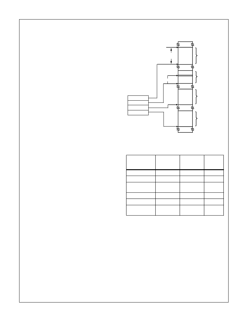
Memory Organization
The processor provides a 20-bit address to memory, which
locates the byte being referenced. The memory is organized
as a linear array of up to 1 million bytes, addressed as
00000(H) to FFFFF(H). The memory is logically divided into
code, data, extra and stack segments of up to 64K bytes
each, with each segment falling on 16-byte boundaries. (See
Figure 1).
All memory references are made relative to base addresses
contained in high speed segment registers. The segment
types were chosen based on the addressing needs of pro-
grams. The segment register to be selected is automatically
chosen according to the specific rules of Table 1. All informa-
tion in one segment type share the same logical attributes
(e.g. code or data). By structuring memory into re-locatable
areas of similar characteristics and by automatically select-
ing segment registers, programs are shorter, faster and
more structured. (See Table 1).
Word (16-bit) operands can be located on even or odd
address boundaries and are thus, not constrained to even
boundaries as is the case in many 16-bit computers. For
address and data operands, the least significant byte of the
word is stored in the lower valued address location and the
most significant byte in the next higher address location. The
BIU automatically performs the proper number of memory
TABLE 1.
TYPE OF
MEMORY
REFERENCE
DEFAULT
SEGMENT
BASE
ALTERNATE
SEGMENT
BASE
OFFSET
Instruction Fetch
CS
None
IP
Stack Operation
SS
None
SP
Variable (except
following)
DS
CS, ES, SS
Effective
Address
String Source
DS
CS, ES, SS
SI
String Destination
ES
None
DI
BP Used As Base
Register
SS
CS, DS, ES
Effective
Address
SEGMENT
REGISTER FILE
CS
SS
DS
ES
64K-BIT
+ OFFSET
FFFFFH
CODE SEGMENT
XXXXOH
STACK SEGMENT
DATA SEGMENT
EXTRA SEGMENT
00000H
FIGURE 1. 80C86 MEMORY ORGANIZATION
80C86
相关PDF资料 |
PDF描述 |
|---|---|
| IS80C88-2 | CMOS 8/16-Bit Microprocessor |
| IS82C50A-5 | CMOS Asynchronous Communications Element |
| IS82C52 | CMOS Serial Controller Interface |
| IS82C54 | CMOS Programmable Interval Timer |
| IS82C54-10 | CMOS Programmable Interval Timer |
相关代理商/技术参数 |
参数描述 |
|---|---|
| IS80C86-2R2490 | 制造商:Rochester Electronics LLC 功能描述:- Bulk |
| IS80C88 | 制造商:Rochester Electronics LLC 功能描述:- Bulk |
| IS80C88-2 | 制造商:Rochester Electronics LLC 功能描述:- Bulk |
| IS80D | 制造商:IDEC CORPORATION 功能描述:SENS.IND. 2W/F 24-230VAC NC |
| IS80DK | 制造商:IDEC CORPORATION 功能描述:SENS.IND. 2W/F 24-230VAC NC |
发布紧急采购,3分钟左右您将得到回复。