参数资料
| 型号: | ISL12026AIVZ-T |
| 厂商: | Intersil |
| 文件页数: | 3/24页 |
| 文件大小: | 0K |
| 描述: | IC RTC/CALENDAR EEPROM 8-TSSOP |
| 标准包装: | 2,500 |
| 类型: | 时钟/日历 |
| 特点: | 警报器,闰年 |
| 时间格式: | HH:MM:SS(12/24 小时) |
| 数据格式: | YY-MM-DD-dd |
| 接口: | I²C,2 线串口 |
| 电源电压: | 2.7 V ~ 5.5 V |
| 电压 - 电源,电池: | 1.8 V ~ 5.5 V |
| 工作温度: | -40°C ~ 85°C |
| 安装类型: | 表面贴装 |
| 封装/外壳: | 8-TSSOP(0.173",4.40mm 宽) |
| 供应商设备封装: | 8-TSSOP |
| 包装: | 带卷 (TR) |
11
FN8231.9
November 30, 2010
INT Register: Interrupt Control and
Frequency Output Register
IM, AL1E, AL0E - Interrupt Control and Status Bits
There are two Interrupt Control bits, Alarm 1 Interrupt Enable
(AL1E) and Alarm 0 Interrupt Enable (AL0E) to specifically
enable or disable the alarm interrupt signal output
(IRQ/FOUT). The interrupts are enabled when either the
AL1E or AL0E or both bits are set to ‘1’ and both the FO1
and FO0 bits are set to 0 (FOUT disabled).
The IM bit enables the pulsed interrupt mode. To enter this
mode, the AL0E or AL1E bits are set to “1”, and the IM bit to
“1”. The IRQ/FOUT output will now be pulsed each time an
alarm occurs. This means that once the interrupt mode alarm
is set, it will continue to alarm for each occurring match of the
alarm and present time. This mode is convenient for hourly or
daily hardware interrupts in microcontroller applications such
as security cameras or utility meter reading.
In the case that both Alarm 0 and Alarm 1 are enabled, the
IRQ/FOUT pin will be pulsed each time either alarm matches
the RTC (both alarms can provide hardware interrupt). If the
IM bit is also set to "1", the IRQ/FOUT will be pulsed for each
of the alarms as well.
FO1, FO0 - Programmable Frequency Output Bits
These are two output control bits. They select one of three
divisions of the internal oscillator, that is applied to the
this output. When using this function, the Alarm output
function is disabled.
Oscillator Compensation Registers
There are two trimming options.
ATR. Analog Trimming Register
DTR. Digital Trimming Register
These registers are non-volatile. The combination of analog
and digital trimming can give up to -64 to +110 ppm of total
adjustment.
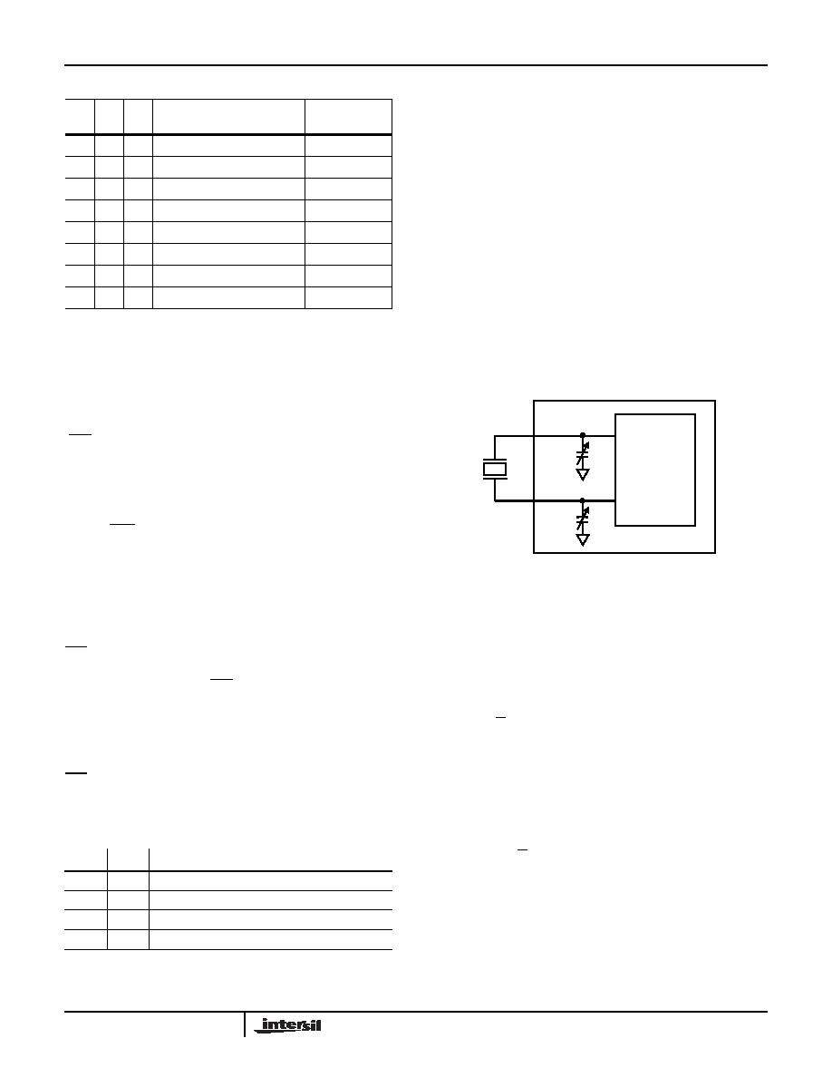
ATR Register - ATR5, ATR4, ATR3, ATR2, ATR1,
ATR0: Analog Trimming Register
6 analog trimming bits, ATR0 to ATR5, are provided in order
to adjust the on-chip load capacitance value for frequency
compensation of the RTC. Each bit has a different weight for
capacitance adjustment. For example, using a Citizen CFS-
206 crystal with different ATR bit combinations provides an
estimated ppm adjustment range from -34 to +80ppm to the
nominal frequency compensation.
The effective on-chip series load capacitance, CLOAD,
ranges from 4.5pF to 20.25pF with a mid-scale value of
12.5pF (default). CLOAD is changed via two digitally
controlled capacitors, CX1 and CX2, connected from the X1
The effective series load capacitance is the combination of
CX1 and CX2:
For example, CLOAD(ATR = 00000) = 12.5pF, CLOAD
(ATR = 100000) = 4.5pF, and CLOAD(ATR = 011111) = 20.25pF.
The entire range for the series combination of load capacitance
goes from 4.5pF to 20.25pF in 0.25pF steps. Note that these
are typical values.
TABLE 3.
BP2
BP1
BP0
PROTECTED ADDRESSES
ISL12026
ARRAY LOCK
0
None (Default)
None
0
1
180h – 1FFh
Upper 1/4
0
1
0
100h – 1FFh
Upper 1/2
0
1
000h – 1FFh
Full Array
10
0
000h – 03Fh
First 4 Pages
10
1
000h – 07Fh
First 8 Pages
1
0
000h – 0FFh
First 16 Pages
1
000h – 1FFh
Full Array
TABLE 4. PROGRAMMABLE FREQUENCY OUTPUT BITS
FO1
FO0
OUTPUT FREQUENCY
0
Alarm output (FOUT disabled)
0
1
32.768kHz
1
0
4096Hz
11
1Hz
FIGURE 8. DIAGRAM OF ATR
CX1
X1
X2
CRYSTAL
OSCILLATOR
CX2
C
X
16 b5
8b4
4 b3
2b2
1 b1
0.5b0
9
+
+
+
+
+
+
()pF
=
(EQ. 1)
C
LOAD
1
C
X1
-----------
1
C
X2
-----------
+
-----------------------------------
=
C
LOAD
16 b5
8 b4
4 b3
2 b2
1 b1
0.5 b0
9
+
+
+
+
+
+
2
-----------------------------------------------------------------------------------------------------------------------------
pF
=
(EQ. 2)
ISL12026, ISL12026A
相关PDF资料 |
PDF描述 |
|---|---|
| VE-J0B-MZ | CONVERTER MOD DC/DC 95V 25W |
| ISL12026AIBZ-T | IC RTC/CALENDAR EEPROM 8-SOIC |
| MCP4331-503E/ML | IC DGTL POT QUAD 50K 20QFN |
| MCP4451-103E/ST | IC POT 10K QUAD 8BIT 20TSSOP |
| VE-23K-MY-F3 | CONVERTER MOD DC/DC 40V 50W |
相关代理商/技术参数 |
参数描述 |
|---|---|
| ISL12026AW | 制造商:Intersil Corporation 功能描述:INKED WAFER SALE, BACKLAP TO 8 MILS, NO INSPECTION REQ. - Rail/Tube |
| ISL12026IBZ | 功能描述:实时时钟 REAL TIME CLOCK/CALE NDARW/ EEPROM IN 8LD RoHS:否 制造商:Microchip Technology 功能:Clock, Calendar. Alarm RTC 总线接口:I2C 日期格式:DW:DM:M:Y 时间格式:HH:MM:SS RTC 存储容量:64 B 电源电压-最大:5.5 V 电源电压-最小:1.8 V 最大工作温度:+ 85 C 最小工作温度: 安装风格:Through Hole 封装 / 箱体:PDIP-8 封装:Tube |
| ISL12026IBZ-T | 功能描述:实时时钟 REAL TIME CLK/CLNDR W/EEPROM IN 8LD RoHS:否 制造商:Microchip Technology 功能:Clock, Calendar. Alarm RTC 总线接口:I2C 日期格式:DW:DM:M:Y 时间格式:HH:MM:SS RTC 存储容量:64 B 电源电压-最大:5.5 V 电源电压-最小:1.8 V 最大工作温度:+ 85 C 最小工作温度: 安装风格:Through Hole 封装 / 箱体:PDIP-8 封装:Tube |
| ISL12026IBZ-T7A | 功能描述:实时时钟 REAL TIME CLK/CLNDR W/EEPROM IN 8LD RoHS:否 制造商:Microchip Technology 功能:Clock, Calendar. Alarm RTC 总线接口:I2C 日期格式:DW:DM:M:Y 时间格式:HH:MM:SS RTC 存储容量:64 B 电源电压-最大:5.5 V 电源电压-最小:1.8 V 最大工作温度:+ 85 C 最小工作温度: 安装风格:Through Hole 封装 / 箱体:PDIP-8 封装:Tube |
| ISL12026IVZ | 功能描述:实时时钟 REAL TIME CLK/CLNDR W/EEPROM IN 8LD RoHS:否 制造商:Microchip Technology 功能:Clock, Calendar. Alarm RTC 总线接口:I2C 日期格式:DW:DM:M:Y 时间格式:HH:MM:SS RTC 存储容量:64 B 电源电压-最大:5.5 V 电源电压-最小:1.8 V 最大工作温度:+ 85 C 最小工作温度: 安装风格:Through Hole 封装 / 箱体:PDIP-8 封装:Tube |
发布紧急采购,3分钟左右您将得到回复。