参数资料
| 型号: | ISL12027IV27AZ |
| 厂商: | Intersil |
| 文件页数: | 9/28页 |
| 文件大小: | 0K |
| 描述: | IC RTC/CALENDAR EEPROM 8-TSSOP |
| 产品培训模块: | Solutions for Industrial Control Applications |
| 标准包装: | 960 |
| 类型: | 时钟/日历 |
| 特点: | 警报器,闰年,监控器,监视计时器 |
| 时间格式: | HH:MM:SS(12/24 小时) |
| 数据格式: | YY-MM-DD-dd |
| 接口: | I²C,2 线串口 |
| 电源电压: | 2.7 V ~ 5.5 V |
| 电压 - 电源,电池: | 1.8 V ~ 5.5 V |
| 工作温度: | -40°C ~ 85°C |
| 安装类型: | 表面贴装 |
| 封装/外壳: | 8-TSSOP(0.173",4.40mm 宽) |
| 供应商设备封装: | 8-TSSOP |
| 包装: | 管件 |
第1页第2页第3页第4页第5页第6页第7页第8页当前第9页第10页第11页第12页第13页第14页第15页第16页第17页第18页第19页第20页第21页第22页第23页第24页第25页第26页第27页第28页
17
FN8232.8
August 12, 2010
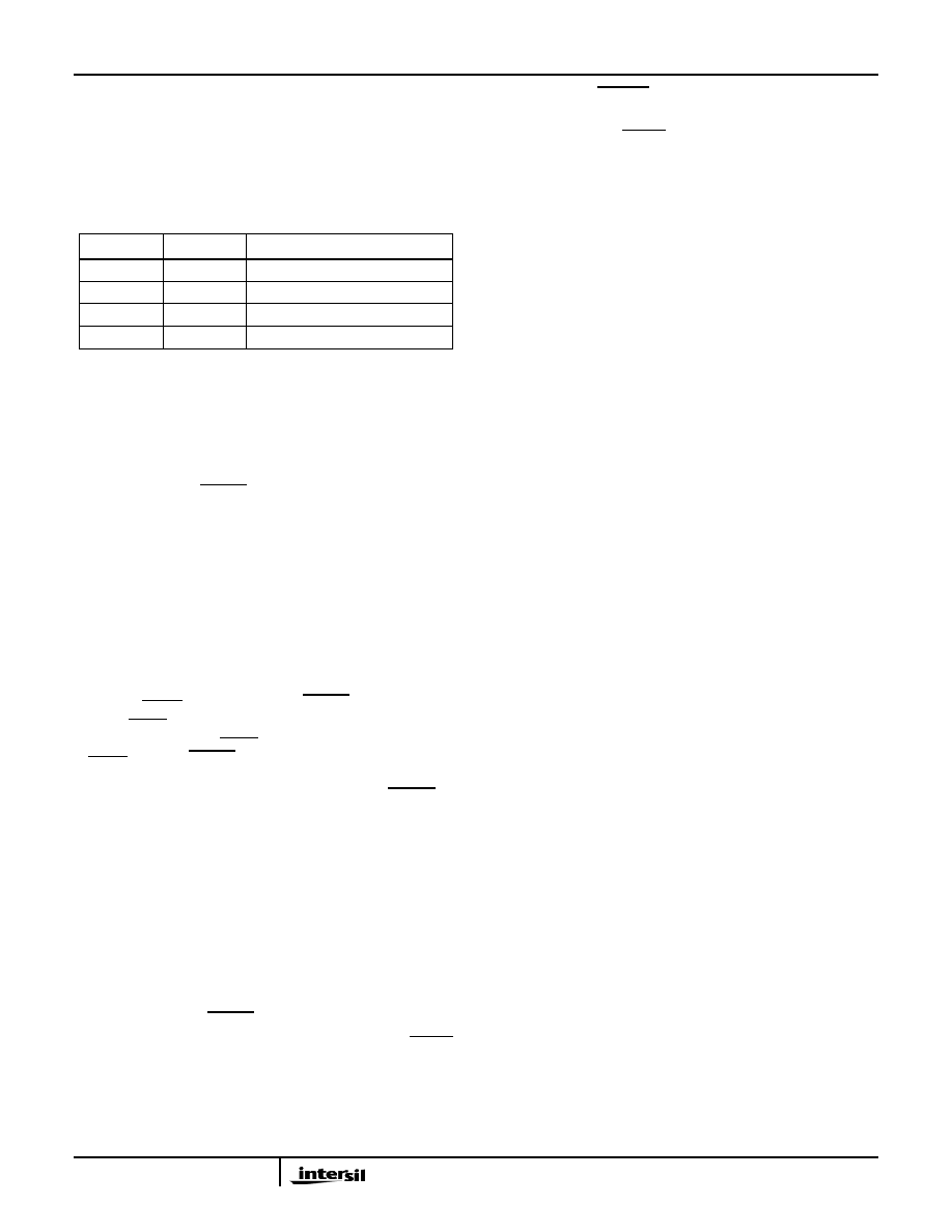
Watchdog Timer Operation
The Watchdog timer timeout period is selectable. By writing
a value to WD1 and WD0, the Watchdog timer can be set to
3 different time out periods or off. When the Watchdog timer
is set to off, the watchdog circuit is configured for low power
operation (see Table 7).
Watchdog Timer Restart
The Watchdog Timer is started by a falling edge of SDA
when the SCL line is high (START condition). The start
signal restarts the watchdog timer counter, resetting the
period of the counter back to the maximum. If another
START fails to be detected prior to the Watchdog timer
expiration, then the RESET pin becomes active for one reset
time out period. In the event that the start signal occurs
during a reset time out period, the start will have no effect.
When using a single START to refresh Watchdog timer, a
STOP condition should be followed to reset the device back
to stand-by mode.(see Figure 3).
In battery mode, the Watchdog timer function is disabled.
Low Voltage Reset (LVR) Operation
When a power failure occurs, a voltage comparator
compares the level of the VDD line versus a preset threshold
voltage (VRESET), then generates a RESET pulse if it is
below VRESET. The reset pulse will timeout 250ms after the
VDD line rises above VRESET. If the VDD remains below
VRESET, then the RESET output will remain asserted low.
Power-up and power-down waveforms are shown in
Figure 4. The LVR circuit is to be designed so the RESET
signal is valid down to VDD = 1.0V.
When the LVR signal is active, unless the part has been
switched into the battery mode
, the completion of an
in-progress non-volatile write cycle is unaffected, allowing a
non-volatile write to continue as long as possible (down to
the Reset Valid Voltage). The LVR signal, when active, will
terminate any in-progress communications to the device and
prevents new commands from disrupting any current write
operations. See “I2C Communications During Battery
Backup and LVR Operation” on page 24.
In battery mode, the RESET signal output is asserted LOW
when the VDD voltage supply has dipped below the VRESET
threshold. The RESET signal output will not return HIGH
until the device is back to VDD mode even if the VDD
voltage is above VRESET threshold.
Serial Communication
Interface Conventions
The device supports the I2C Protocol.
Clock and Data
Data states on the SDA line can change only during SCL
LOW. SDA state changes during SCL HIGH are reserved for
indicating start and stop conditions. (see Figure 16).
Start Condition
All commands are preceded by the start condition, which is a
HIGH to LOW transition of SDA when SCL is HIGH. The
device continuously monitors the SDA and SCL lines for the
start condition and will not respond to any command until
this condition has been met. (see Figure 17).
Stop Condition
All communications must be terminated by a stop condition,
which is a LOW to HIGH transition of SDA when SCL is
HIGH. The stop condition is also used to place the device
into the Standby power mode after a read sequence. A stop
condition can only be issued after the transmitting device
has released the bus. (see Figure 17).
Acknowledge
Acknowledge is a software convention used to indicate
successful data transfer. The transmitting device, either
master or slave, will release the bus after transmitting 8-bits.
During the ninth clock cycle, the receiver will pull the SDA
line LOW to acknowledge that it received the 8-bits of data.
Refer to Figure 18.
The device will respond with an acknowledge after
recognition of a start condition and if the correct Device
Identifier and Select bits are contained in the Slave Address
Byte. If a write operation is selected, the device will respond
with an acknowledge after the receipt of each subsequent
8-bit word. The device will not acknowledge if the slave
address byte is incorrect.
In the read mode, the device will transmit 8-bits of data,
release the SDA line, then monitor the line for an
acknowledge. If an acknowledge is detected and no stop
condition is generated by the master, the device will continue
to transmit data. The device will terminate further data
transmissions if an acknowledge is not detected. The master
must then issue a stop condition to return the device to
Standby mode and place the device into a known state.
TABLE 7.
WD1
WD0
DURATION
1
disabled
1
0
250ms
0
1
750ms
0
1.75s
ISL12027, ISL12027A
相关PDF资料 |
PDF描述 |
|---|---|
| ISL12028IVZ | IC RTC/CALENDAR EEPROM 14-TSSOP |
| ISL12029IVZ | IC RTC/CALENDAR EEPROM 14-TSSOP |
| ISL12030IBZ | IC RTC/CALENDAR EEPROM 8-SOIC |
| ISL12032IVZ | IC RTC LP BATT BACK SRAM 14TSSOP |
| ISL12057IUZ | IC RTC/CALENDAR I2C 8-MSOP |
相关代理商/技术参数 |
参数描述 |
|---|---|
| ISL12027IV27AZ-T | 功能描述:实时时钟 REAL TIME CLK/CLNDR W/EEPROM 2 92VSET RoHS:否 制造商:Microchip Technology 功能:Clock, Calendar. Alarm RTC 总线接口:I2C 日期格式:DW:DM:M:Y 时间格式:HH:MM:SS RTC 存储容量:64 B 电源电压-最大:5.5 V 电源电压-最小:1.8 V 最大工作温度:+ 85 C 最小工作温度: 安装风格:Through Hole 封装 / 箱体:PDIP-8 封装:Tube |
| ISL12027IV27Z | 功能描述:实时时钟 REAL TIME CLK/CLNDR W/EEPROM 2 7VSET RoHS:否 制造商:Microchip Technology 功能:Clock, Calendar. Alarm RTC 总线接口:I2C 日期格式:DW:DM:M:Y 时间格式:HH:MM:SS RTC 存储容量:64 B 电源电压-最大:5.5 V 电源电压-最小:1.8 V 最大工作温度:+ 85 C 最小工作温度: 安装风格:Through Hole 封装 / 箱体:PDIP-8 封装:Tube |
| ISL12027IV27Z-T | 功能描述:实时时钟 REAL TIME CLK/CLNDR W/EEPROM 2 7VSET 8 RoHS:否 制造商:Microchip Technology 功能:Clock, Calendar. Alarm RTC 总线接口:I2C 日期格式:DW:DM:M:Y 时间格式:HH:MM:SS RTC 存储容量:64 B 电源电压-最大:5.5 V 电源电压-最小:1.8 V 最大工作温度:+ 85 C 最小工作温度: 安装风格:Through Hole 封装 / 箱体:PDIP-8 封装:Tube |
| ISL12027IV30AZ | 功能描述:实时时钟 REAL TIME CLK/CLNDR W/EEPROM 3 09VSET RoHS:否 制造商:Microchip Technology 功能:Clock, Calendar. Alarm RTC 总线接口:I2C 日期格式:DW:DM:M:Y 时间格式:HH:MM:SS RTC 存储容量:64 B 电源电压-最大:5.5 V 电源电压-最小:1.8 V 最大工作温度:+ 85 C 最小工作温度: 安装风格:Through Hole 封装 / 箱体:PDIP-8 封装:Tube |
| ISL12027IV30AZ-T | 功能描述:实时时钟 REAL TIME CLK/CLNDR W/EEPROM 3 09VSET RoHS:否 制造商:Microchip Technology 功能:Clock, Calendar. Alarm RTC 总线接口:I2C 日期格式:DW:DM:M:Y 时间格式:HH:MM:SS RTC 存储容量:64 B 电源电压-最大:5.5 V 电源电压-最小:1.8 V 最大工作温度:+ 85 C 最小工作温度: 安装风格:Through Hole 封装 / 箱体:PDIP-8 封装:Tube |
发布紧急采购,3分钟左右您将得到回复。