参数资料
| 型号: | ISL12029AIV27Z-T |
| 厂商: | Intersil |
| 文件页数: | 17/29页 |
| 文件大小: | 0K |
| 描述: | IC RTC/CALENDAR EEPROM 14TSSOP |
| 产品培训模块: | Solutions for Industrial Control Applications |
| 标准包装: | 2,500 |
| 类型: | 时钟/日历 |
| 特点: | 警报器,闰年,监控器,监视计时器 |
| 时间格式: | HH:MM:SS(12/24 小时) |
| 数据格式: | YY-MM-DD-dd |
| 接口: | I²C,2 线串口 |
| 电源电压: | 2.7 V ~ 5.5 V |
| 电压 - 电源,电池: | 1.8 V ~ 5.5 V |
| 工作温度: | -40°C ~ 85°C |
| 安装类型: | 表面贴装 |
| 封装/外壳: | 14-TSSOP(0.173",4.40mm 宽) |
| 供应商设备封装: | 14-TSSOP |
| 包装: | 带卷 (TR) |
第1页第2页第3页第4页第5页第6页第7页第8页第9页第10页第11页第12页第13页第14页第15页第16页当前第17页第18页第19页第20页第21页第22页第23页第24页第25页第26页第27页第28页第29页
24
FN6206.10
December 16, 2010
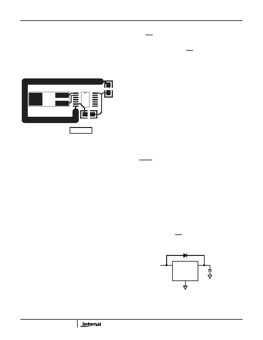
Layout Considerations
The crystal input at X1 has a very high impedance and will
pick up high frequency signals from other circuits on the
board. Since the X2 pin is tied to the other side of the crystal,
it is also a sensitive node. These signals can couple into the
oscillator circuit and produce double clocking or misclocking,
seriously affecting the accuracy of the RTC. Care needs to
be taken in layout of the RTC circuit to avoid noise pickup.
Figure 27 shows a suggested layout for the ISL12029
device.
The X1 and X2 connections to the crystal are to be kept as
short as possible. A thick ground trace around the crystal is
advised to minimize noise intrusion, but ground near the X1
and X2 pins should be avoided as it will add to the load
capacitance at those pins. Keep in mind these guidelines for
other PCB layers in the vicinity of the RTC device. A small
decoupling capacitor at the VDD pin of the chip is mandatory,
with a solid connection to ground.
For other RTC products, the same rules stated above should
be observed, but adjusted slightly since the packages and
pinouts are slightly different.
Oscillator Measurements
When a proper crystal is selected and the layout guidelines
above are observed, the oscillator should start-up in most
circuits in less than one second. Some circuits may take slightly
longer, but start-up should definitely occur in less than 5s.
When testing RTC circuits, the most common impulse is to
apply a scope probe to the circuit at the X2 pin (oscillator
output) and observe the waveform. DO NOT DO THIS!
Although in some cases you may see a usable waveform, due
to the parasitics (usually 10pF to ground) applied with the
scope probe, there will be no useful information in that
waveform other than the fact that the circuit is oscillating. The
X2 output is sensitive to capacitive impedance so the voltage
levels and the frequency will be affected by the parasitic
elements in the scope probe. Applying a scope probe can
possibly cause a faulty oscillator to start-up, hiding other issues
(although in the Intersil RTCs, the internal circuitry assures
start-up when using the proper crystal and layout).
The best way to analyze the RTC circuit is to power it up and
read the real time clock as time advances, or if the chip has
the IRQ/FOUT output, look at the output of that pin on an
oscilloscope (after enabling it with the control register, and
using a pull-up resistor for the open-drain output).
Alternatively, the ISL12029 IRQ/FOUT- output can be
checked by setting an alarm for each minute. Using the
pulse interrupt mode setting, the once-per-minute interrupt
functions are an indication of proper oscillation.
Backup Battery Operation
Many types of batteries can be used with the Intersil RTC
products. 3.0V or 3.6V Lithium batteries are appropriate, and
sizes are available that can power a Intersil RTC device for up
to 10 years. Another option is to use a supercapacitor for
applications where VDD may disappear intermittently for short
periods of time. Depending on the value of supercapacitor
used, backup time can last from a few days to two weeks (with
>1F). A simple silicon or Schottky barrier diode can be used in
series with VDD to charge the supercapacitor, which is
connected to the VBAT pin. Try to use Schottky diodes with
very low leakages, <1A desirable. Do not use the diode to
charge a battery (especially lithium batteries!).
Note that whether a battery or supercap is used, if the VBAT
voltage drops below the data sheet minimum of 1.8V and the
VDD power cycles to 0V then back to VDD voltage, then the
RESET output may stay low and the I2C communications will
not operate. The VBAT and VDD power will need to be cycled
to 0V together to allow normal operation again.
There are two possible modes for battery backup operation,
Standard and Legacy mode. In Standard mode, there are no
operational concerns when switching over to battery backup
since all other devices functions are disabled. Battery drain
is minimal in Standard mode, and return to Normal VDD
powered operation is predictable. In Legacy modes the VBAT
pin can power the chip if the voltage is above VDD and
VTRIP. This makes it possible to generate alarms and
communicate with the device under battery backup, but the
supply current drain is much higher than the Standard mode
and backup time is reduced. In this case if alarms are used
in backup mode, the IRQ/FOUT pull-up resistor must be
connected to VBAT voltage source. During initial power-up
the default mode is the Standard mode.
FIGURE 27. SUGGESTED LAYOUT FOR INTERSIL RTC IN
SO-14
C1
0.1
F
XTAL1
U1
R1 10k
X1228
32.768kGz
ISL12029
C1
0.1F
R1 10k
XTAL
32.768kGz
U1
FIGURE 28. SUPERCAPACITOR CHARGING CIRCUIT
VDD
VBAT
VSS
2.7V TO 5.5V
SUPERCAPACITOR
ISL12029, ISL12029A
相关PDF资料 |
PDF描述 |
|---|---|
| ISL12029AIB27Z-T | IC RTC/CALENDAR EEPROM 14SOIC |
| ISL12028AIV27Z-T | IC RTC/CALENDAR EEPROM 14TSSOP |
| VE-B3L-MY-F1 | CONVERTER MOD DC/DC 28V 50W |
| DS1337U/T&R | IC RTC SERIAL 2WIRE LP 8-USOP |
| DS1337S/T&R | IC RTC SERIAL 2WIRE LP 8-SOIC |
相关代理商/技术参数 |
参数描述 |
|---|---|
| ISL12029IB27AZ | 功能描述:实时时钟 REAL TIME CLKRTC W/ EPROM 2 92VSET 14 RoHS:否 制造商:Microchip Technology 功能:Clock, Calendar. Alarm RTC 总线接口:I2C 日期格式:DW:DM:M:Y 时间格式:HH:MM:SS RTC 存储容量:64 B 电源电压-最大:5.5 V 电源电压-最小:1.8 V 最大工作温度:+ 85 C 最小工作温度: 安装风格:Through Hole 封装 / 箱体:PDIP-8 封装:Tube |
| ISL12029IB27AZ-T | 功能描述:实时时钟 REAL TIME CLKRTC W/ EPROM 2 92VSET 14 RoHS:否 制造商:Microchip Technology 功能:Clock, Calendar. Alarm RTC 总线接口:I2C 日期格式:DW:DM:M:Y 时间格式:HH:MM:SS RTC 存储容量:64 B 电源电压-最大:5.5 V 电源电压-最小:1.8 V 最大工作温度:+ 85 C 最小工作温度: 安装风格:Through Hole 封装 / 箱体:PDIP-8 封装:Tube |
| ISL12029IB27Z | 功能描述:实时时钟 REAL TIME CLKRTC W/ EPROM 2 7VSET 14 RoHS:否 制造商:Microchip Technology 功能:Clock, Calendar. Alarm RTC 总线接口:I2C 日期格式:DW:DM:M:Y 时间格式:HH:MM:SS RTC 存储容量:64 B 电源电压-最大:5.5 V 电源电压-最小:1.8 V 最大工作温度:+ 85 C 最小工作温度: 安装风格:Through Hole 封装 / 箱体:PDIP-8 封装:Tube |
| ISL12029IB27Z-T | 功能描述:实时时钟 REAL TIME CLKRTC W/ EPROM 2 7VSET 14 L RoHS:否 制造商:Microchip Technology 功能:Clock, Calendar. Alarm RTC 总线接口:I2C 日期格式:DW:DM:M:Y 时间格式:HH:MM:SS RTC 存储容量:64 B 电源电压-最大:5.5 V 电源电压-最小:1.8 V 最大工作温度:+ 85 C 最小工作温度: 安装风格:Through Hole 封装 / 箱体:PDIP-8 封装:Tube |
| ISL12029IB30AZ | 功能描述:实时时钟 REAL TIME CLKRTC W/ EPROM 3 09VSET 14 RoHS:否 制造商:Microchip Technology 功能:Clock, Calendar. Alarm RTC 总线接口:I2C 日期格式:DW:DM:M:Y 时间格式:HH:MM:SS RTC 存储容量:64 B 电源电压-最大:5.5 V 电源电压-最小:1.8 V 最大工作温度:+ 85 C 最小工作温度: 安装风格:Through Hole 封装 / 箱体:PDIP-8 封装:Tube |
发布紧急采购,3分钟左右您将得到回复。