参数资料
| 型号: | ISL12082IUZ |
| 厂商: | Intersil |
| 文件页数: | 7/26页 |
| 文件大小: | 0K |
| 描述: | IC RTC I2C LO-POWER 10-MSOP |
| 标准包装: | 50 |
| 类型: | 时钟/日历 |
| 特点: | 警报器,闰年,监视计时器 |
| 时间格式: | HH:MM:SS:hh(12/24 小时) |
| 数据格式: | YY-MM-DD-dd |
| 接口: | I²C,2 线串口 |
| 电源电压: | 2.7 V ~ 5.5 V |
| 电压 - 电源,电池: | 1.8 V ~ 5.5 V |
| 工作温度: | -40°C ~ 85°C |
| 安装类型: | 表面贴装 |
| 封装/外壳: | 10-TFSOP,10-MSOP(0.118",3.00mm 宽) |
| 供应商设备封装: | 10-MSOP |
| 包装: | 管件 |
15
FN6731.3
November 24, 2008
alarm register, multiple registers, or all registers can be
enabled for a match.
There are two alarm operation modes: Single Event and
Periodic Interrupt Mode:
Single Event Mode is enabled by setting the ALME bit to
“1”, the IM bit to “0”, and IRQ1E bit to “1” and/or IRQ2E bit
to “0”. This mode permits a one-time match between the
alarm registers and the RTC registers. Once this match
occurs, the ALM status bit is set to “1” and the IRQ1/fOUT
and/or IRQ2 output will be pulled low and will remain low
until the ALM status bit is reset to “0”. This can be done
manually or by using the auto-reset feature.
Periodic Interrupt Mode is enabled by setting the ALME
bit to “1”, the IM bit to “1”, and IRQ1E bit to “1” and/or
IRQ2E bit to “0”. The IRQ1/fOUT and/or IRQ2 output will
now be pulsed each time an alarm occurs. This means
that once the interrupt mode alarm is set, it will continue to
alarm for each occurring match of the alarm and present
time. This mode is convenient for hourly or daily hardware
interrupts in microcontroller applications such as security
cameras or utility meter reading.
To clear an alarm, the ALM status bit must be set to “0” with
a write. Note that if the ARST bit is set to “1” (address 07h,
Bit 7), the ALM bit will automatically be cleared when the
status register is read.
Following are examples of both Single Event and periodic
Interrupt Mode alarms.
Example 1 – Alarm set with single interrupt (IM = ”0”)
A single alarm will occur on January 1 at 11:30am.
A. Set Alarm registers as follows:
B. Set the ALME bit as follows:
After these registers are set, an alarm will be generated when
the RTC advances to exactly 11:30am on January 1 (after
seconds changes from 59 to 00) by setting the ALM bit in the
status register to “1” and also bringing the IRQ1/fOUT and
IRQ2 output low if IRQ1E bit is set to “1” and IRQ2E bit is set
to “0”.
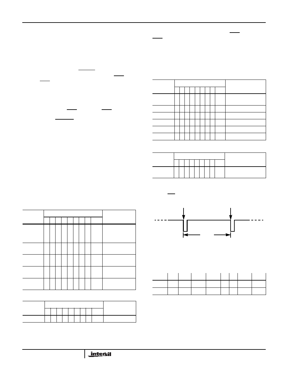
Example 2 – Pulsed interrupt once per minute (IM = ”1”)
Interrupts at one minute intervals when the seconds register
is at 30s.
A. Set alarm registers as follows:
B. Set the Interrupt register as follows:
Once the registers are set, the following waveform will be
seen at IRQ:
Note that the status register ALM bit will be set each time the
alarm is triggered, but does not need to be read or cleared.
Timer Control Register (TMRC) [Address 09h]
TIMER CLOCK FREQUENCY SELECTION BITS
(TCLK <1:0>)
For detailed timer operation, please refer to “TIMER
COUNTER OPERATION” on page 17.
These bits select the Timer/Watchdog clock frequency for
the Timer Counter Register (TCNT, address 13h) and the
internal Sub-Timer Counter Register (TSCNT). When the
ALARM
REGISTER
BIT
DESCRIPTION
76
543210
HEX
SCA
0
000000
00h
Seconds disabled
MNA
1
0
110000
B0h Minutes set to 30,
enabled
HRA
10
010001
91h
Hours set to 11,
enabled
DTA
1
0
000001
81h
Date set to 1,
enabled
MOA
1
0
000001
81h
Month set to 1,
enabled
DWA
0
000000
00h
Day of week
disabled
CONTROL
REGISTER
BIT
DESCRIPTION
7654
3210
HEX
INT
0
1
x
0000
x0hEnable Alarm
NOTE: x indicate other control bits
ALARM
REGISTER
BIT
DESCRIPTION
76543210 HEX
SCA
10110000 B0h Seconds set to 30,
enabled
MNA
00000000 00h Minutes disabled
HRA
00000000 00h Hours disabled
DTA
00000000 00h Date disabled
MOA
00000000 00h Month disabled
DWA
00000000 00h Day of week disabled
CONTROL
REGISTER
BIT
DESCRIPTION
76543210 HEX
INT
1 1 x x 0000
x0hEnable Alarm and Int
Mode
NOTE: x indicate other control bits
TABLE 9. TIMER CONTROL REGISTER (TMRC)
ADDR
7
6
5
4
3
2
1
0
09h
TIM TMRE TMOD1 TMOD0
0
TCLK1 TCLK0
Default
0
60s
RTC AND ALARM REGISTERS ARE BOTH 30s
ISL12082
相关PDF资料 |
PDF描述 |
|---|---|
| ISL1208IU8-TK | IC RTC/CALENDAR I2C 8-MSOP |
| ISL1209IU10-TK | IC RTC/CALENDAR I2C 10-MSOP |
| ISL1218IUZ | IC RTC LP BATT BACKED SRAM 8MSOP |
| ISL1219IUZ-T | IC RTC LP BATT BACK SRAM 10MSOP |
| ISL1220IUZ | IC RTC LP BATT BACK SRAM 10MSOP |
相关代理商/技术参数 |
参数描述 |
|---|---|
| ISL12082IUZ-T | 功能描述:实时时钟 RTC W/RESEAL ALARM & TIMR FUNCTNS IN MSO RoHS:否 制造商:Microchip Technology 功能:Clock, Calendar. Alarm RTC 总线接口:I2C 日期格式:DW:DM:M:Y 时间格式:HH:MM:SS RTC 存储容量:64 B 电源电压-最大:5.5 V 电源电压-最小:1.8 V 最大工作温度:+ 85 C 最小工作温度: 安装风格:Through Hole 封装 / 箱体:PDIP-8 封装:Tube |
| ISL1208EVAL | 功能描述:电源管理IC开发工具 EVALRD FOR ISL1208 RoHS:否 制造商:Maxim Integrated 产品:Evaluation Kits 类型:Battery Management 工具用于评估:MAX17710GB 输入电压: 输出电压:1.8 V |
| ISL1208IB8 | 功能描述:IC RTC/CALENDAR I2C 8-SOIC RoHS:否 类别:集成电路 (IC) >> 时钟/计时 - 实时时钟 系列:- 产品培训模块:Obsolescence Mitigation Program 标准包装:1 系列:- 类型:时钟/日历 特点:警报器,闰年,SRAM 存储容量:- 时间格式:HH:MM:SS(12/24 小时) 数据格式:YY-MM-DD-dd 接口:SPI 电源电压:2 V ~ 5.5 V 电压 - 电源,电池:- 工作温度:-40°C ~ 85°C 安装类型:表面贴装 封装/外壳:8-WDFN 裸露焊盘 供应商设备封装:8-TDFN EP 包装:管件 |
| ISL1208IB8-TK | 功能描述:IC RTC/CALENDAR I2C 8-SOIC RoHS:否 类别:集成电路 (IC) >> 时钟/计时 - 实时时钟 系列:- 产品培训模块:Obsolescence Mitigation Program 标准包装:1 系列:- 类型:时钟/日历 特点:警报器,闰年,SRAM 存储容量:- 时间格式:HH:MM:SS(12/24 小时) 数据格式:YY-MM-DD-dd 接口:SPI 电源电压:2 V ~ 5.5 V 电压 - 电源,电池:- 工作温度:-40°C ~ 85°C 安装类型:表面贴装 封装/外壳:8-WDFN 裸露焊盘 供应商设备封装:8-TDFN EP 包装:管件 |
| ISL1208IB8Z | 功能描述:实时时钟 I2C REAL TIME CLOCK/ CALENDAR 8LD RoHS:否 制造商:Microchip Technology 功能:Clock, Calendar. Alarm RTC 总线接口:I2C 日期格式:DW:DM:M:Y 时间格式:HH:MM:SS RTC 存储容量:64 B 电源电压-最大:5.5 V 电源电压-最小:1.8 V 最大工作温度:+ 85 C 最小工作温度: 安装风格:Through Hole 封装 / 箱体:PDIP-8 封装:Tube |
发布紧急采购,3分钟左右您将得到回复。