参数资料
| 型号: | ISL1208IB8Z-T7A |
| 厂商: | Intersil |
| 文件页数: | 11/24页 |
| 文件大小: | 0K |
| 描述: | IC RTC/CALENDAR I2C LP 8SOIC |
| 标准包装: | 250 |
| 类型: | 时钟/日历 |
| 特点: | 警报器,闰年,SRAM |
| 存储容量: | 2B |
| 时间格式: | HH:MM:SS(12/24 小时) |
| 数据格式: | YY-MM-DD-dd |
| 接口: | I²C,2 线串口 |
| 电源电压: | 2.7 V ~ 5.5 V |
| 电压 - 电源,电池: | 1.8 V ~ 5.5 V |
| 工作温度: | -40°C ~ 85°C |
| 安装类型: | 表面贴装 |
| 封装/外壳: | 8-SOIC(0.154",3.90mm 宽) |
| 供应商设备封装: | 8-SOIC |
| 包装: | 带卷 (TR) |
19
FN8085.8
September 12, 2008
A system to implement temperature compensation would
consist of the ISL1208, a temperature sensor, and a
microcontroller. These devices may already be in the system
so the function will just be a matter of implementing software
and performing some calculations. Fairly accurate
temperature compensation can be implemented just by
using the crystal manufacturer’s specifications for the
turnover temperature T0 and the drift coefficient (β). The
formula for calculating the oscillator adjustment necessary is
Equation 3:
Once the temperature curve for a crystal is established, then
the designer should decide at what discrete temperatures
the compensation will change. Since drift is higher at
extreme temperatures, the compensation may not be
needed until the temperature is greater than +20°C from T0.
A sample curve of the ATR setting vs Frequency Adjustment
for the ISL1208 and a typical RTC crystal is given in
Figure 18. This curve may vary with different crystals, so it is
good practice to evaluate a given crystal in an ISL1208
circuit before establishing the adjustment values.
This curve is then used to figure what ATR and DTR settings
are used for compensation. The results would be placed in a
lookup table for the microcontroller to access.
Note that the ATR register affects the FOUT frequency
directly. Also, the DTR setting will affect the FOUT frequency
for all but the 32.768Khz setting, due to the clock correction
in the divider chain.
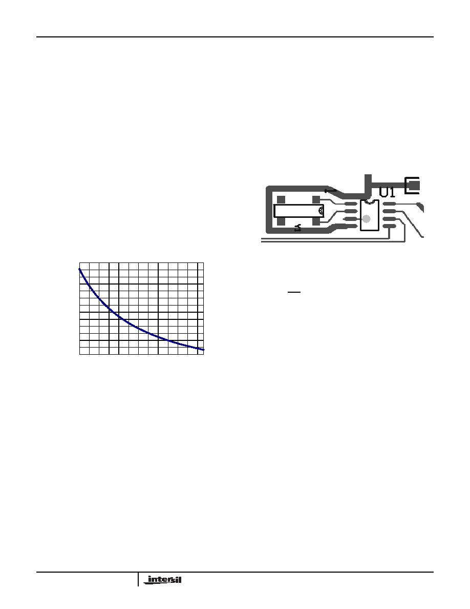
Layout Considerations
The crystal input at X1 has a very high impedance, and
oscillator circuits operating at low frequencies such as
32.768kHz are known to pick up noise very easily if layout
precautions are not followed. Most instances of erratic
clocking or large accuracy errors can be traced to the
susceptibility of the oscillator circuit to interference from
adjacent high speed clock or data lines. Careful layout of the
RTC circuit will avoid noise pickup and insure accurate
clocking.
Figure 19 shows a suggested layout for the ISL1208 device
using a surface mount crystal. Two main precautions should
be followed:
1. Do not run the serial bus lines or any high speed logic
lines in the vicinity of the crystal. These logic level lines
can induce noise in the oscillator circuit to cause
misclocking.
2. Add a ground trace around the crystal with one end
terminated at the chip ground. This will provide
termination for emitted noise in the vicinity of the RTC
device.
In addition, it is a good idea to avoid a ground plane under
the X1 and X2 pins and the crystal, as this will affect the load
capacitance and therefore the oscillator accuracy of the
circuit. If the IRQ/FOUT pin is used as a clock, it should be
routed away from the RTC device as well. The traces for the
VBAT and VCC pins can be treated as a ground, and should
be routed around the crystal.
Battery Backup Considerations
The ISL1208 device provides a VBAT pin which is used for a
battery backup input. The battery voltage can vary from 1.8V
up to 5.5V, independent of the VDD supply voltage. An
internal switch automatically connects the VBAT supply to
the to the internal power node when VDD power goes away,
and switches back to VDD when power returns.
Since this battery switch draws power from the battery, it is
very low power and not very fast. If the VDD drops too
quickly to 0V, there is not enough time for the switch to
connect the VBAT source to the internal power node, and the
SRAM contents can be lost or corrupted. It is a good idea to
keep power-down ramps longer than 50us to insure data
retention.
Battery drain can be minimized by using the LPMODE
option. Since normally the VBAT and VDD need to be
monitored in order to switch at the lower voltage, two
comparator function are needed during battery backup.
LPMODE shuts off one of the comparators and just
compares VDD to VBAT to activate switchover. This saves
about 500nA of VBAT current at 3.0V. Do not use LPMODE
when VBAT ≥ VDD - 0.2V, to avoid permanently placing the
device in battery backup mode.
Adjustment(ppm)
T
0
–
()2
=
β
(EQ. 3)
-40
-30
-20
-10
0
10
20
30
40
50
60
70
80
90
0
5
10 15 20 25 30 35 40 45 50 55 60
ATR SETTING
PP
M
ADJUSTME
N
T
FIGURE 18. ATR SETTING vs OSCILLATOR FREQUENCY
ADJUSTMENT
FIGURE 19. SUGGESTED LAYOUT FOR ISL1208 AND
CRYSTAL
ISL1208
相关PDF资料 |
PDF描述 |
|---|---|
| ISL1218IUZ-T | IC RTC LP BATT BACKED SRAM 8MSOP |
| VE-B3K-MY-F3 | CONVERTER MOD DC/DC 40V 50W |
| ADN2850BCPZ25 | IC RHEO DGTL 10B DL 25K 16LFCSP |
| VE-B3K-MY-F1 | CONVERTER MOD DC/DC 40V 50W |
| ADN2850BCPZ250 | IC DGTL RHEO DL 1024POS 16LFCSP |
相关代理商/技术参数 |
参数描述 |
|---|---|
| ISL1208IB8Z-TK | 功能描述:实时时钟 I2C REAL TIME CLOCK/ CALENDAR 8LD RoHS:否 制造商:Microchip Technology 功能:Clock, Calendar. Alarm RTC 总线接口:I2C 日期格式:DW:DM:M:Y 时间格式:HH:MM:SS RTC 存储容量:64 B 电源电压-最大:5.5 V 电源电压-最小:1.8 V 最大工作温度:+ 85 C 最小工作温度: 安装风格:Through Hole 封装 / 箱体:PDIP-8 封装:Tube |
| ISL1208IB8Z-TKR5291 | 功能描述:实时时钟 I2CAL TIME CLK/CLNDR BATRY MODE TESTS RoHS:否 制造商:Microchip Technology 功能:Clock, Calendar. Alarm RTC 总线接口:I2C 日期格式:DW:DM:M:Y 时间格式:HH:MM:SS RTC 存储容量:64 B 电源电压-最大:5.5 V 电源电压-最小:1.8 V 最大工作温度:+ 85 C 最小工作温度: 安装风格:Through Hole 封装 / 箱体:PDIP-8 封装:Tube |
| ISL1208IRT8Z | 功能描述:实时时钟 I2CAL TIME CLK/CLNDR 8LD 3X3 RoHS:否 制造商:Microchip Technology 功能:Clock, Calendar. Alarm RTC 总线接口:I2C 日期格式:DW:DM:M:Y 时间格式:HH:MM:SS RTC 存储容量:64 B 电源电压-最大:5.5 V 电源电压-最小:1.8 V 最大工作温度:+ 85 C 最小工作温度: 安装风格:Through Hole 封装 / 箱体:PDIP-8 封装:Tube |
| ISL1208IRT8Z-TK | 功能描述:实时时钟 I2CAL TIME CLK/CLNDR 8LD 3X3 RoHS:否 制造商:Microchip Technology 功能:Clock, Calendar. Alarm RTC 总线接口:I2C 日期格式:DW:DM:M:Y 时间格式:HH:MM:SS RTC 存储容量:64 B 电源电压-最大:5.5 V 电源电压-最小:1.8 V 最大工作温度:+ 85 C 最小工作温度: 安装风格:Through Hole 封装 / 箱体:PDIP-8 封装:Tube |
| ISL1208IU8 | 功能描述:IC RTC LP BATT BACKED SRAM 8MSOP RoHS:否 类别:集成电路 (IC) >> 时钟/计时 - 实时时钟 系列:- 产品培训模块:Obsolescence Mitigation Program 标准包装:1 系列:- 类型:时钟/日历 特点:警报器,闰年,SRAM 存储容量:- 时间格式:HH:MM:SS(12/24 小时) 数据格式:YY-MM-DD-dd 接口:SPI 电源电压:2 V ~ 5.5 V 电压 - 电源,电池:- 工作温度:-40°C ~ 85°C 安装类型:表面贴装 封装/外壳:8-WDFN 裸露焊盘 供应商设备封装:8-TDFN EP 包装:管件 |
发布紧急采购,3分钟左右您将得到回复。