参数资料
| 型号: | ISL1208IU8-TK |
| 厂商: | Intersil |
| 文件页数: | 5/24页 |
| 文件大小: | 0K |
| 描述: | IC RTC/CALENDAR I2C 8-MSOP |
| 标准包装: | 1,000 |
| 类型: | 时钟/日历 |
| 特点: | 警报器,闰年,SRAM |
| 存储容量: | 2B |
| 时间格式: | HH:MM:SS(12/24 小时) |
| 数据格式: | YY-MM-DD-dd |
| 接口: | I²C,2 线串口 |
| 电源电压: | 2.7 V ~ 5.5 V |
| 电压 - 电源,电池: | 1.8 V ~ 5.5 V |
| 工作温度: | -40°C ~ 85°C |
| 安装类型: | 表面贴装 |
| 封装/外壳: | 8-TSSOP,8-MSOP(0.118",3.00mm 宽) |
| 供应商设备封装: | 8-MSOP |
| 包装: | 带卷 (TR) |
13
FN8085.8
September 12, 2008
FREQUENCY OUT CONTROL BITS (FO <3:0>)
These bits enable/disable the frequency output function and
select the output frequency at the IRQ/fOUT pin. See
Table 4 for frequency selection. When the frequency mode is
enabled, it will override the alarm mode at the IRQ/fOUT pin.
FREQUENCY OUTPUT AND INTERRUPT BIT (FOBATB)
This bit enables/disables the fOUT/IRQ pin during battery
backup mode (i.e. VBAT power source active). When the
FOBATB is set to “1” the fOUT/IRQ pin is disabled during
battery backup mode. This means that both the frequency
output and alarm output functions are disabled. When the
FOBATB is cleared to “0”, the fOUT/IRQ pin is enabled
during battery backup mode.
LOW POWER MODE BIT (LPMODE)
This bit enables/disables low power mode. With
LPMODE = “0”, the device will be in normal mode and the
VBAT supply will be used when VDD < VBAT - VBATHYS and
VDD < VTRIP. With LPMODE = “1”, the device will be in low
power mode and the VBAT supply will be used when
VDD < VBAT -VBATHYS. There is a supply current saving of
about 600nA when using LPMODE = “1” with VDD = 5V.
with LPMODE ON and OFF.) Avoid setting the device into
low power mode with VDD < VBAT, the I2C communications
will stop permanently. The VBAT input must be lowered
below VDD to resume communications.
ALARM ENABLE BIT (ALME)
This bit enables/disables the alarm function. When the ALME
bit is set to “1”, the alarm function is enabled. When the ALME
is cleared to “0”, the alarm function is disabled. The alarm
function can operate in either a single event alarm or a periodic
interrupt alarm (see IM bit).
NOTE: When the frequency output mode is enabled, the alarm function
is disabled.
INTERRUPT/ALARM MODE BIT (IM)
This bit enables/disables the interrupt mode of the alarm
function. When the IM bit is set to “1”, the alarm will operate
in the interrupt mode, where an active low pulse width of
250ms will appear at the IRQ/fOUT pin when the RTC is
triggered by the alarm as defined by the alarm registers (0Ch
to 11h). When the IM bit is cleared to “0”, the alarm will
operate in standard mode, where the IRQ/fOUT pin will be
tied low until the ALM status bit is cleared to “0”.
Analog Trimming Register
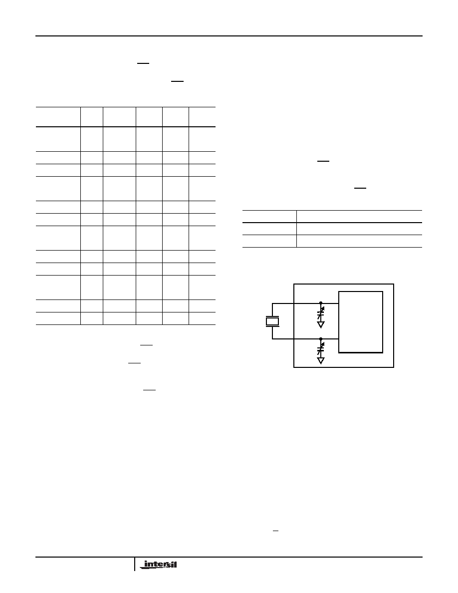
ANALOG TRIMMING REGISTER (ATR<5:0>)
Six analog trimming bits, ATR0 to ATR5, are provided in
order to adjust the on-chip load capacitance value for
frequency compensation of the RTC. Each bit has a different
weight for capacitance adjustment. For example, using a
Citizen CFS-206 crystal with different ATR bit combinations
provides an estimated ppm adjustment range from -34ppm
to +80ppm to the nominal frequency compensation. The
combination of analog and digital trimming can give up to
-94ppm to +140ppm of total adjustment.
The effective on-chip series load capacitance, CLOAD,
ranges from 4.5pF to 20.25pF with a mid-scale value of
12.5pF (default). CLOAD is changed via two digitally
controlled capacitors, CX1 and CX2, connected from the X1
and X2 pins to ground (see Figure 11). The value of CX1 and
TABLE 4. FREQUENCY SELECTION OF fOUT PIN
FREQUENCY,
fOUT
UNITS
FO3
FO2
FO1
FO0
0
Hz
0
000
32768
Hz
0
1
4096
Hz
0
1
0
1024
Hz
0
1
64
Hz
0
100
32
Hz
0
101
16
Hz
0
110
8
Hz
0
111
4
Hz
1
000
2
Hz
1
001
1
Hz
1
010
1/2
Hz
1
011
1/4
Hz
1
100
1/8
Hz
1
101
1/16
Hz
1
0
1/32
Hz
1
IM BIT
INTERRUPT/ALARM FREQUENCY
0
Single Time Event Set By Alarm
1
Repetitive/Recurring Time Event Set By Alarm
FIGURE 11. DIAGRAM OF ATR
CX1
X1
X2
CRYSTAL
OSCILLATOR
CX2
C
X
16 b5
8b4
4 b3
2b2
1 b1
0.5b0
9
+
+
+
+
+
+
()pF
=
(EQ. 1)
ISL1208
相关PDF资料 |
PDF描述 |
|---|---|
| ISL1209IU10-TK | IC RTC/CALENDAR I2C 10-MSOP |
| ISL1218IUZ | IC RTC LP BATT BACKED SRAM 8MSOP |
| ISL1219IUZ-T | IC RTC LP BATT BACK SRAM 10MSOP |
| ISL1220IUZ | IC RTC LP BATT BACK SRAM 10MSOP |
| ISL1221IUZ | IC RTC LP BATT BACK SRAM 10MSOP |
相关代理商/技术参数 |
参数描述 |
|---|---|
| ISL1208IU8Z | 功能描述:实时时钟 I2C REAL TIME CLOCK/ CALENDAR 8LD RoHS:否 制造商:Microchip Technology 功能:Clock, Calendar. Alarm RTC 总线接口:I2C 日期格式:DW:DM:M:Y 时间格式:HH:MM:SS RTC 存储容量:64 B 电源电压-最大:5.5 V 电源电压-最小:1.8 V 最大工作温度:+ 85 C 最小工作温度: 安装风格:Through Hole 封装 / 箱体:PDIP-8 封装:Tube |
| ISL1208IU8Z-T7A | 功能描述:实时时钟 I2CAL TIME CLK/CLNDR 8LD RoHS:否 制造商:Microchip Technology 功能:Clock, Calendar. Alarm RTC 总线接口:I2C 日期格式:DW:DM:M:Y 时间格式:HH:MM:SS RTC 存储容量:64 B 电源电压-最大:5.5 V 电源电压-最小:1.8 V 最大工作温度:+ 85 C 最小工作温度: 安装风格:Through Hole 封装 / 箱体:PDIP-8 封装:Tube |
| ISL1208IU8Z-TK | 功能描述:实时时钟 I2CAL TIME CLK/CLNDR 8LD RoHS:否 制造商:Microchip Technology 功能:Clock, Calendar. Alarm RTC 总线接口:I2C 日期格式:DW:DM:M:Y 时间格式:HH:MM:SS RTC 存储容量:64 B 电源电压-最大:5.5 V 电源电压-最小:1.8 V 最大工作温度:+ 85 C 最小工作温度: 安装风格:Through Hole 封装 / 箱体:PDIP-8 封装:Tube |
| ISL1209 | 制造商:INTERSIL 制造商全称:Intersil Corporation 功能描述:Low Power RTC with Battery Backed SRAM and Event Detection |
| ISL1209_06 | 制造商:INTERSIL 制造商全称:Intersil Corporation 功能描述:Low Power RTC with Battery Backed SRAM and Event Detection |
发布紧急采购,3分钟左右您将得到回复。