参数资料
| 型号: | ISL1221IUZ |
| 厂商: | Intersil |
| 文件页数: | 5/24页 |
| 文件大小: | 0K |
| 描述: | IC RTC LP BATT BACK SRAM 10MSOP |
| 产品培训模块: | Solutions for Industrial Control Applications |
| 标准包装: | 980 |
| 类型: | 时间事件记录器 |
| 特点: | 警报器,闰年,SRAM |
| 存储容量: | 2B |
| 时间格式: | HH:MM:SS(12/24 小时) |
| 数据格式: | YY-MM-DD-dd |
| 接口: | I²C,2 线串口 |
| 电源电压: | 2.7 V ~ 5.5 V |
| 电压 - 电源,电池: | 1.8 V ~ 5.5 V |
| 工作温度: | -40°C ~ 85°C |
| 安装类型: | 表面贴装 |
| 封装/外壳: | 10-TFSOP,10-MSOP(0.118",3.00mm 宽) |
| 供应商设备封装: | 10-MSOP |
| 包装: | 管件 |
13
FN6316.1
July 15, 2010
Real Time Clock Registers
Addresses [00h to 06h]
RTC REGISTERS (SC, MN, HR, DT, MO, YR, DW)
These registers depict BCD representations of the time. As
such, SC (Seconds) and MN (Minutes) range from 0 to 59,
HR (Hour) can either be a 12-hour or 24-hour mode, DT
(Date) is 1 to 31, MO (Month) is 1 to 12, YR (Year) is 0 to 99,
and DW (Day of the Week) is 0 to 6.
The DW register provides a Day of the Week status and uses
three bits DW2 to DW0 to represent the seven days of the
week. The counter advances in the cycle 0-1-2-3-4-5-6-0-1-
2-… The assignment of a numerical value to a specific day
of the week is arbitrary and may be decided by the system
software designer. The default value is defined as “0”.
24 HOUR TIME
If the MIL bit of the HR register is “1”, the RTC uses a
24-hour format. If the MIL bit is “0”, the RTC uses a 12-hour
format and HR21 bit functions as an AM/PM indicator with a
“1” representing PM. The clock defaults to 12-hour format
time with HR21 = “0”.
LEAP YEARS
Leap years add the day February 29 and are defined as those
years that are divisible by 4. Years divisible by 100 are not leap
years, unless they are also divisible by 400. This means that
the year 2000 is a leap year, the year 2100 is not. The ISL1221
does not correct for the leap year in the year 2100.
Control and Status Registers
Addresses [07h to 0Bh]
The Control and Status Registers consist of the Status
Register, Interrupt and Alarm Register, Analog Trimming and
Digital Trimming Registers.
Status Register (SR)
The Status Register is located in the memory map at
address 07h. This is a volatile register that provides either
control or status of RTC failure, battery mode, alarm trigger,
event detection, write protection of clock counter, crystal
oscillator enable and auto reset of status bits.
REAL TIME CLOCK FAIL BIT (RTCF)
This bit is set to a “1” after a total power failure. This is a read
only bit that is set by hardware (ISL1221 internally) when the
device powers up after having lost all power to the device.
The bit is set regardless of whether VDD or VBAT is applied
first. The loss of only one of the supplies does not set the
RTCF bit to “1”. The first valid write to the RTC section after
a complete power failure resets the RTCF bit to “0” (writing
one byte is sufficient).
BATTERY BIT (BAT)
This bit is set to a “1” when the device enters battery backup
mode. This bit can be reset either manually by the user or
automatically reset by enabling the auto-reset bit (see “Auto
Reset Enable Bit (ARST)” on page 14). A write to this bit in
the SR can only set it to “0”, not “1”.
ALARM BIT (ALM)
These bits announce if the alarm matches the real time
clock. If there is a match, the respective bit is set to “1”. This
bit can be manually reset to “0” by the user or automatically
reset by enabling the auto-reset bit (see ARST bit). A write to
this bit in the SR can only set it to “0”, not “1”.
NOTE: An alarm bit that is set by an alarm occurring during an SR
read operation will remain set after the read operation is complete.
EVENT DETECT BIT (EVT)
The event detect bit indicates status of the event input pin
(EVIN). When the Event Detect function is enabled and the
EVIN pin is triggered, the EVT bit is set to “1” to indicate a
detection of an event, and the Time Stamp Register records
the current RTC time. A write to this bit in the SR can only
set it to “0” not “1”.
When a HIGH signal is present at the EVIN pin (or a LOW to
HIGH transition), an “event” is detected. On detection the
EVT bit is set HIGH, the open drain EVDET pin is asserted
(pulled LOW), and the RTC time is recorded in the Time
Stamp registers. The EVT bit will be reset to LOW:
When the EVT bit is set to 0 with a Status Register write
When there is a read from the Status Register, with the
ARST bit set to “1” (auto-reset enabled).
If the EVT bit has not been cleared, only the initial (first
occurrence) Timestamp is retained in the Timestamp
register, subsequent triggers of the EVIN pin will not record
new timestamps. If the EVT bit is cleared to “0”, the
Timestamp register will record the time of the next event
went the EVIN pin is triggered.
WRITE RTC ENABLE BIT (WRTC)
The WRTC bit enables or disables write capability into the
RTC Timing Registers. The factory default setting of this bit
is “0”. Upon initialization or power up, the WRTC must be set
to “1” to enable the RTC. Upon the completion of a valid
write (STOP), the RTC starts counting. The RTC internal
1Hz signal is synchronized to the STOP condition during a
valid write cycle.
CRYSTAL OSCILLATOR ENABLE BIT (XTOSCB)
This bit enables/disables the internal crystal oscillator. When
the XTOSCB is set to “1”, the oscillator is disabled, and the
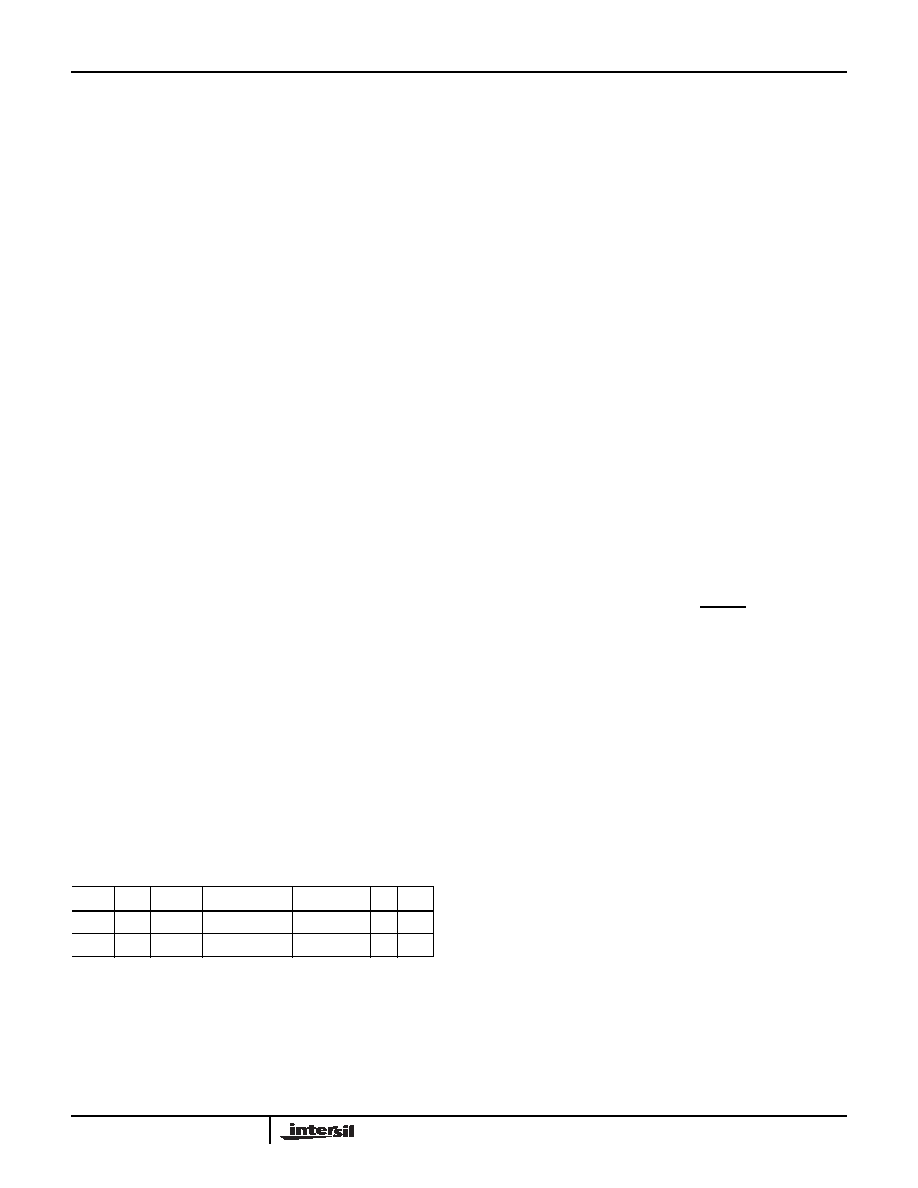
TABLE 6. STATUS REGISTER (SR)
ADDR
7
6
5
4
3
2
1
0
07h
ARST XTOSCB reserved WRTC
EVT
ALM BAT RTCF
Default
0
000
0
ISL1221
相关PDF资料 |
PDF描述 |
|---|---|
| ISL26134AVZ | IC ADC 24BIT SRL 80SPS 28TSSOP |
| ISL26319FVZ-T7A | IC ADC 12BIT SRL/SPI 16TSSOP |
| ISL26329FVZ | IC ADC 12BIT SPI/SRL 16-TSSOP |
| ISL2671286IBZ | IC ADC 12BIT SPI/SRL 20K 8SOIC |
| ISL26712IRTZ | IC ADC 12BIT SAR 1MSPS 8-TDFN |
相关代理商/技术参数 |
参数描述 |
|---|---|
| ISL1221IUZ-T | 功能描述:实时时钟 REAL TIME CLKRTC IN RoHS:否 制造商:Microchip Technology 功能:Clock, Calendar. Alarm RTC 总线接口:I2C 日期格式:DW:DM:M:Y 时间格式:HH:MM:SS RTC 存储容量:64 B 电源电压-最大:5.5 V 电源电压-最小:1.8 V 最大工作温度:+ 85 C 最小工作温度: 安装风格:Through Hole 封装 / 箱体:PDIP-8 封装:Tube |
| ISL14010 | 制造商:INTERSIL 制造商全称:Intersil Corporation 功能描述:Low Jitter Clock Generators for Set-Top Box |
| ISL14010IRZ | 功能描述:时钟合成器/抖动清除器 REAL TIME CLKRTC 16LD 3X3 RoHS:否 制造商:Skyworks Solutions, Inc. 输出端数量: 输出电平: 最大输出频率: 输入电平: 最大输入频率:6.1 GHz 电源电压-最大:3.3 V 电源电压-最小:2.7 V 封装 / 箱体:TSSOP-28 封装:Reel |
| ISL14010IRZ-T | 功能描述:实时时钟 REAL TIME CLKRTC 16LD 3X3 RoHS:否 制造商:Microchip Technology 功能:Clock, Calendar. Alarm RTC 总线接口:I2C 日期格式:DW:DM:M:Y 时间格式:HH:MM:SS RTC 存储容量:64 B 电源电压-最大:5.5 V 电源电压-最小:1.8 V 最大工作温度:+ 85 C 最小工作温度: 安装风格:Through Hole 封装 / 箱体:PDIP-8 封装:Tube |
| ISL14011 | 制造商:INTERSIL 制造商全称:Intersil Corporation 功能描述:Low Jitter Clock Generators for Set-Top Box |
发布紧急采购,3分钟左右您将得到回复。