参数资料
| 型号: | ISL22444WFV20Z |
| 厂商: | Intersil |
| 文件页数: | 6/19页 |
| 文件大小: | 0K |
| 描述: | IC POT DGTL 256TP LN LP 20-TSSOP |
| 产品培训模块: | Solutions for Test and Measurement Equipment Solutions for Industrial Control Applications |
| 标准包装: | 74 |
| 系列: | XDCP™ |
| 接片: | 256 |
| 电阻(欧姆): | 10k |
| 电路数: | 4 |
| 温度系数: | 标准值 ±85 ppm/°C |
| 存储器类型: | 非易失 |
| 接口: | 4 线 SPI(芯片选择) |
| 电源电压: | 2.25 V ~ 5.5 V |
| 工作温度: | -40°C ~ 125°C |
| 安装类型: | 表面贴装 |
| 封装/外壳: | 20-TSSOP(0.173",4.40mm 宽) |
| 供应商设备封装: | 20-TSSOP |
| 包装: | 管件 |
| 产品目录页面: | 1237 (CN2011-ZH PDF) |
14
FN6426.0
May 24, 2007
Applications Information
Communicating with ISL22444
Communication with ISL22444 proceeds using SPI interface
through the ACR (address 10000b), IVRi (address 00000b,
00001b, 00010b or 00011b), WRi (addresses 00000b,
00001b, 00010b or 00011b) and General Purpose registers
(addresses from 00100b to 01110b).
The wiper position of each potentiometer is controlled by the
corresponding WRi register. Writes and reads can be made
directly to these registers to control and monitor the wiper
position without any non-volatile memory changes. This is
done by setting MSB bit at address 10000b to 1 (ACR[7] = 1).
The non-volatile IVRi stores the power up position of the
wiper. IVRi is accessible when MSB bit at address 10000b is
set to 0 (ACR[7] = 0). Writing a new value to the IVRi register
will set a new power up position for the wiper. Also, writing to
this register will load the same value into the corresponding
WRi as the IVRi. Reading from the IVRi will not change the
WRi, if its contents are different.
Daisy Chain Configuration
When application needs more then one ISL22444, it can
communicate with all of them without additional CS lines by
daisy chaining the DCPs as shown on Figure 18. In Daisy
Chain configuration the SDO pin of previous chip is
connected to SDI pin of the following chip, and each CS and
SCK pins are connected to the corresponding
microcontroller pins in parallel, like regular SPI interface
implementation. The Daisy Chain configuration can also be
used for simultaneous setting of multiple DCPs. Note, the
number of daisy chained DCPs is limited only by the driving
capabilities of SCK and CS pins of microcontroller; for larger
number of SPI devices buffering of SCK and CS lines is
required.
Daisy Chain Write Operation
The write operation starts by HIGH to LOW transition on CS
line, followed by N two bytes write instructions on SDI line
with reversed chain access sequence: the instruction byte +
data byte for the last DCP in chain is going first, as shown on
Figure 19. The serial data is going through DCPs from DCP0
to DCP(N-1) as follows: DCP0 --> DCP1 --> DCP2 --> ... -->
DCP(N-1). The write instruction is executed on the rising
edge of CS for all N DCPs simultaneously.
Daisy Chain Read Operation
The read operation consists of two parts: first, send read
instructions (N two bytes operation) with valid address;
second, read the requested data while sending NOP
instructions (N two bytes operation) as shown on Figure 20
and Figure 21.
The first part starts by HIGH to LOW transition on CS line,
followed by N two bytes read instruction on SDI line with
reversed chain access sequence: the instruction byte +
dummy data byte for the last DCP in chain is going first,
followed by LOW to HIGH transition on CS line. The read
instructions are executed during second part of read
sequence. It also starts by HIGH to LOW transition on CS
line, followed by N two bytes NOP instructions on SDI line
and LOW to HIGH transition of CS. The data is read on
every even byte during second part of read sequence while
every odd byte contains instruction code + address from
which the data is being read.
Wiper Transition
When stepping up through each tap in voltage divider mode,
some tap transition points can result in noticeable voltage
transients, or overshoot/undershoot, resulting from the
sudden transition from a very low impedance “make” to a
much higher impedance “break within an extremely short
period of time (<50ns). Two such code transitions are EFh to
F0h, and 0Fh to 10h. Note, that all switching transients will
settle well within the settling time as stated on the datasheet.
A small capacitor can be added externally to reduce the
amplitude of these voltage transients, but that will also
reduce the useful bandwidth of the circuit, thus may not be a
good solution for some applications. It may be a good idea,
in that case, to use fast amplifiers in a signal chain for fast
recovery.
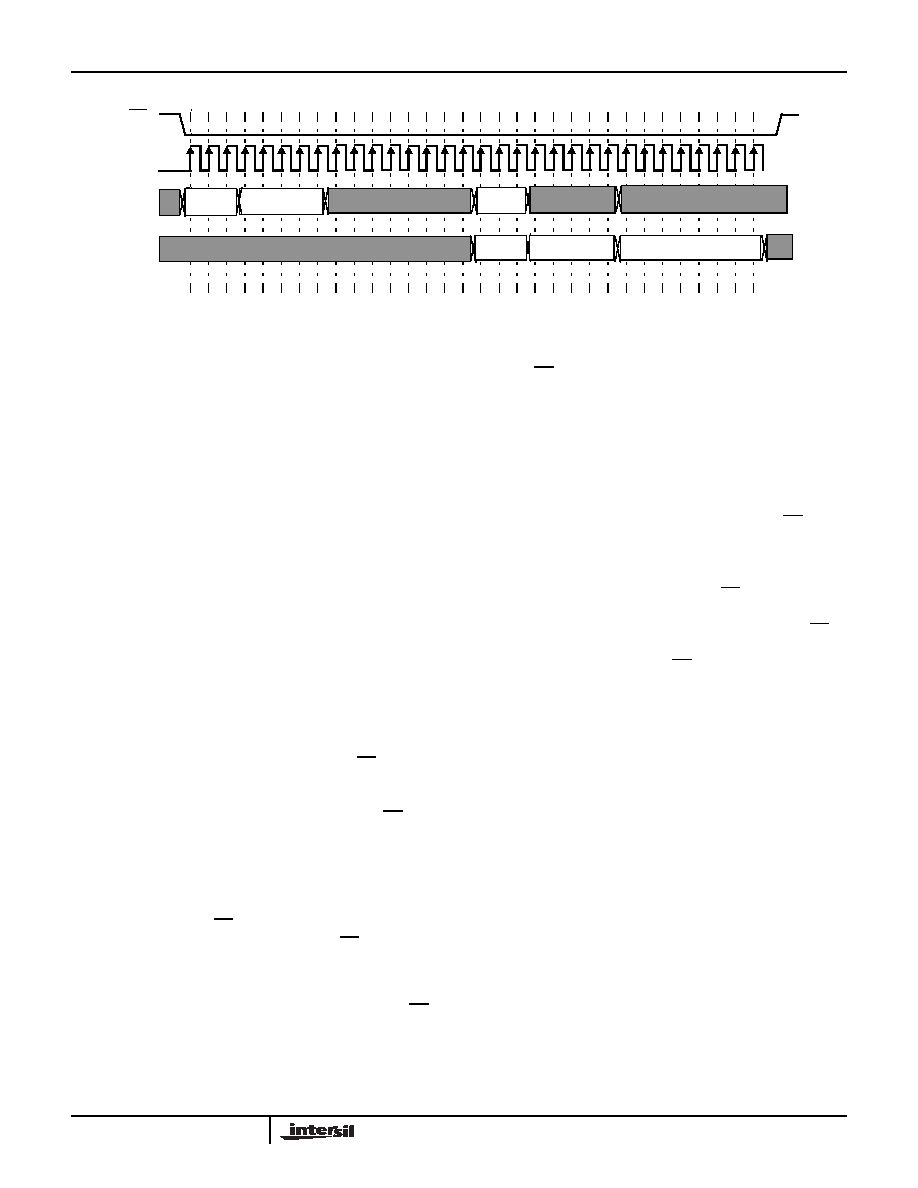
CS
SCK
SDI
SDO
RD
ADDR
NOP
RD
ADDR
READ DATA
1
8
16
24
32
FIGURE 17. FOUR BYTE READ SEQUENCE
ISL22444
相关PDF资料 |
PDF描述 |
|---|---|
| ISL22343WFV20Z | IC POT DGTL 256TP LN LP 20-TSSOP |
| X9317ZS8IZ-2.7 | IC POT DGTL 1K OHM 8-SOIC |
| X9418WV24 | IC DCP DUAL 10K 64TP 24TSSOP |
| X9C503SIZ | IC XDCP 100-TAP 50K EE 8-SOIC |
| X9C102SIZ | IC XDCP 100-TAP 1K EE 8-SOIC |
相关代理商/技术参数 |
参数描述 |
|---|---|
| ISL22444WFV20Z-TK | 功能描述:数字电位计 IC 272 TAP FL RNG IND QD SPI DCP 20LD RoHS:否 制造商:Maxim Integrated 电阻:200 Ohms 温度系数:35 PPM / C 容差:25 % POT 数量:Dual 每 POT 分接头:256 弧刷存储器:Volatile 缓冲刷: 数字接口:Serial (3-Wire, SPI) 描述/功能:Dual Volatile Low Voltage Linear Taper Digital Potentiometer 工作电源电压:1.7 V to 5.5 V 电源电流:27 uA 最大工作温度:+ 125 C 安装风格:SMD/SMT 封装 / 箱体:TQFN-16 封装:Reel |
| ISL22446 | 制造商:INTERSIL 制造商全称:Intersil Corporation 功能描述:Quad Digitally Controlled Potentiometer XDCP |
| ISL22446UFRT20Z | 功能描述:数字电位计 IC 128 TAP FL RNG IND QD DCP 20LD 4X4 TQFN RoHS:否 制造商:Maxim Integrated 电阻:200 Ohms 温度系数:35 PPM / C 容差:25 % POT 数量:Dual 每 POT 分接头:256 弧刷存储器:Volatile 缓冲刷: 数字接口:Serial (3-Wire, SPI) 描述/功能:Dual Volatile Low Voltage Linear Taper Digital Potentiometer 工作电源电压:1.7 V to 5.5 V 电源电流:27 uA 最大工作温度:+ 125 C 安装风格:SMD/SMT 封装 / 箱体:TQFN-16 封装:Reel |
| ISL22446UFRT20Z-TK | 功能描述:数字电位计 IC 128 TAP FL RNG IND QD DCP 20LD 4X4 TQFN RoHS:否 制造商:Maxim Integrated 电阻:200 Ohms 温度系数:35 PPM / C 容差:25 % POT 数量:Dual 每 POT 分接头:256 弧刷存储器:Volatile 缓冲刷: 数字接口:Serial (3-Wire, SPI) 描述/功能:Dual Volatile Low Voltage Linear Taper Digital Potentiometer 工作电源电压:1.7 V to 5.5 V 电源电流:27 uA 最大工作温度:+ 125 C 安装风格:SMD/SMT 封装 / 箱体:TQFN-16 封装:Reel |
| ISL22446UFV20Z | 功能描述:数字电位计 IC 128 TAP FL RNG IND QD DCP 20LD RoHS:否 制造商:Maxim Integrated 电阻:200 Ohms 温度系数:35 PPM / C 容差:25 % POT 数量:Dual 每 POT 分接头:256 弧刷存储器:Volatile 缓冲刷: 数字接口:Serial (3-Wire, SPI) 描述/功能:Dual Volatile Low Voltage Linear Taper Digital Potentiometer 工作电源电压:1.7 V to 5.5 V 电源电流:27 uA 最大工作温度:+ 125 C 安装风格:SMD/SMT 封装 / 箱体:TQFN-16 封装:Reel |
发布紧急采购,3分钟左右您将得到回复。