- 您现在的位置:买卖IC网 > PDF目录383129 > ISL23711UIU10Z (INTERSIL CORP) Terminal Voltage +-3V or +-5V, 128 Taps IC Serial Interface PDF资料下载
参数资料
| 型号: | ISL23711UIU10Z |
| 厂商: | INTERSIL CORP |
| 元件分类: | 数字电位计 |
| 英文描述: | Terminal Voltage +-3V or +-5V, 128 Taps IC Serial Interface |
| 中文描述: | 50K DIGITAL POTENTIOMETER, 2-WIRE SERIAL CONTROL INTERFACE, 128 POSITIONS, PDSO10 |
| 封装: | ROHS COMPLIANT, PLASTIC, MO-187BA, MSOP-10 |
| 文件页数: | 7/9页 |
| 文件大小: | 270K |
| 代理商: | ISL23711UIU10Z |
7
FN6127.0
August 16, 2005
of 127 individual resistors connected in series. At either end
of the array and between each resistor is an electronic
switch that transfers the potential at that point to the wiper.
The wiper, when at either fixed terminal, acts like its
mechanical equivalent and does not move beyond the last
position. That is, the counter does not wrap around when
clocked to either extreme.
The electronic switches on the device operate in a “make
before break” mode when the wiper changes tap positions.
DCP Description
The DCP is implemented with a combination of resistor
elements and CMOS switches. The physical ends of the
DCP are equivalent to the fixed terminals of a mechanical
potentiometer (R
H
and R
L
pins). The R
W
pin is connected to
intermediate nodes, and is equivalent to the wiper terminal
of a mechanical potentiometer. The position of the wiper
terminal is controlled by a 7-bit volatile Wiper Register (WR).
When the WR contains all zeroes (00h), the wiper terminal
(R
W
) is closest to its “Low” terminal (R
L
). When the WR
contains all ones (7Fh), the wiper terminal (R
W
) is closest to
its “High” terminal (R
H
). As the value of the WR increases
from all zeroes (0 decimal) to all ones (127 decimal), the
wiper moves monotonically from the position closest to R
L
to
the position closest to R
H
. At the same time, the resistance
between R
W
and R
L
increases monotonically, while the
resistance between R
H
and R
W
decreases monotonically.
While the ISL23711 is being powered up, the WR is reset to
20h (64 decimal), which locates the R
W
at the center
between R
L
and R
H
.
The WR can be read or written directly using the I
2
C serial
interface as described in the following sections.
Memory Description
A read operation to address 0 outputs the value of the
volatile WR.
A write operation to address 0 only writes to the volatile WR.
I
2
C Serial Interface
The ISL23711 supports a bidirectional bus oriented protocol.
The protocol defines any device that sends data onto the
bus as a transmitter and the receiving device as the receiver.
The device controlling the transfer is a master and the
device being controlled is the slave. The master always
initiates data transfers and provides the clock for both
transmit and receive operations. Therefore, the ISL23711
operates as a slave device in all applications.
All communication over the I
2
C interface is conducted by
sending the MSB of each byte of data first.
Protocol Conventions
Data states on the SDA line can change only during SCL LOW
periods. SDA state changes during SCL HIGH are reserved for
indicating START and STOP conditions (See Figure 1). On
power-up of the ISL23711 the SDA pin is in the input mode.
All I
2
C interface operations must begin with a START condition,
which is a HIGH to LOW transition of SDA while SCL is HIGH.
The ISL23711 continuously monitors the SDA and SCL lines for
the START condition and does not respond to any command
until this condition is met (See Figure 1).
All I
2
C interface operations must be terminated by a STOP
condition, which is a LOW to HIGH transition of SDA while
SCL is HIGH (See Figure 1). A STOP condition at the end of
a read operation, or at the end of a write operation to volatile
bytes only places the device in its standby mode.
An ACK, Acknowledge, is a software convention used to
indicate a successful data transfer. The transmitting device,
either master or slave, releases the SDA bus after
transmitting eight bits. During the ninth clock cycle, the
receiver pulls the SDA line LOW to acknowledge the
reception of the eight bits of data (See Figure 2).
The ISL23711 responds with an ACK after recognition of a
START condition followed by a valid Identification Byte, and
once again after successful receipt of an Address Byte. The
ISL23711 also responds with an ACK after receiving a Data
Byte of a write operation. The master must respond with an
ACK after receiving a Data Byte of a read operation
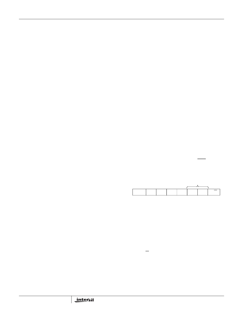
A valid Identification Byte contains 01010 as the five MSBs,
and the following two bits matching the logic values present
at pins A1, and A0. The LSB is in the Read/Write bit. Its
value is “1” for a Read operation, and “0” for a Write
operation. (See Table 1.)
TABLE 1. IDENTIFICATION BYTE FORMAT
Logic values at pins A1, and A0 respectively
Write Operation
A Write operation requires a START condition, followed by a
valid Identification Byte, a valid Address Byte, a Data Byte,
and a STOP condition. After each of the three bytes, the
ISL23711 responds with an ACK.
Read Operation
A Read operation is initiated by a master using the following
sequence: a START, the Identification byte (slave address)
with the R/W bit set to “1”. At the moment of the first
acknowledge by the ISL23711 (slave device), the master-
transmitter becomes a master receiver and receives the data
byte from the slave-transmitter.The Master receives the data
byte and issues a non-acknowledge (SDA is HIGH), then a
STOP to terminate the read operation. Since the ISL 23711
has just one WR, it will transmit only one byte (see Figure 4).
0
1
0
1
0
A1
A0
R/W
(MSB)
(LSB)
ISL23711
相关PDF资料 |
PDF描述 |
|---|---|
| ISL23711WIU10Z | Terminal Voltage +-3V or +-5V, 128 Taps IC Serial Interface |
| ISL23711 | Terminal Voltage +-3V or +-5V, 128 Taps IC Serial Interface |
| ISL24003 | Multi-Channel Buffers Plus VCOM Driver(多通道缓冲器和VCOM驱动器) |
| ISL24006 | 14-Channel Programmable Switchable I2C TFT-LCD Reference Voltage Generator with Integrated 4-Channel Static Gamma Drivers |
| ISL24006IRZ | 14-Channel Programmable Switchable I2C TFT-LCD Reference Voltage Generator with Integrated 4-Channel Static Gamma Drivers |
相关代理商/技术参数 |
参数描述 |
|---|---|
| ISL23711UIU10Z-T | 功能描述:数字电位计 IC ISL23711U DCP 50KOHM SISTANCE OPT IND RoHS:否 制造商:Maxim Integrated 电阻:200 Ohms 温度系数:35 PPM / C 容差:25 % POT 数量:Dual 每 POT 分接头:256 弧刷存储器:Volatile 缓冲刷: 数字接口:Serial (3-Wire, SPI) 描述/功能:Dual Volatile Low Voltage Linear Taper Digital Potentiometer 工作电源电压:1.7 V to 5.5 V 电源电流:27 uA 最大工作温度:+ 125 C 安装风格:SMD/SMT 封装 / 箱体:TQFN-16 封装:Reel |
| ISL23711WIU10Z | 功能描述:数字电位计 IC ISL23711W DCP 10KOHM SISTANCE OPT IND RoHS:否 制造商:Maxim Integrated 电阻:200 Ohms 温度系数:35 PPM / C 容差:25 % POT 数量:Dual 每 POT 分接头:256 弧刷存储器:Volatile 缓冲刷: 数字接口:Serial (3-Wire, SPI) 描述/功能:Dual Volatile Low Voltage Linear Taper Digital Potentiometer 工作电源电压:1.7 V to 5.5 V 电源电流:27 uA 最大工作温度:+ 125 C 安装风格:SMD/SMT 封装 / 箱体:TQFN-16 封装:Reel |
| ISL23711WIU10Z-T | 功能描述:数字电位计 IC ISL23711W DCP 10KOHM SISTANCE OPT IND RoHS:否 制造商:Maxim Integrated 电阻:200 Ohms 温度系数:35 PPM / C 容差:25 % POT 数量:Dual 每 POT 分接头:256 弧刷存储器:Volatile 缓冲刷: 数字接口:Serial (3-Wire, SPI) 描述/功能:Dual Volatile Low Voltage Linear Taper Digital Potentiometer 工作电源电压:1.7 V to 5.5 V 电源电流:27 uA 最大工作温度:+ 125 C 安装风格:SMD/SMT 封装 / 箱体:TQFN-16 封装:Reel |
| ISL24002IRTZ | 功能描述:IC REF VOLT GEN TFT LCD 32-TQFN RoHS:是 类别:集成电路 (IC) >> 线性 - 视频处理 系列:- 标准包装:250 系列:- 类型:电平移位器 应用:LCD 电视机/监控器 安装类型:表面贴装 封装/外壳:28-WFQFN 裸露焊盘 供应商设备封装:28-WQFN(4x4)裸露焊盘 包装:带卷 (TR) 其它名称:296-32523-2TPS65198RUYT-ND |
| ISL24002IRTZ-T13 | 制造商:Intersil Corporation 功能描述:ISL24002IRTZ PBFREE STATIC 14+1 (14 STATIC GAMMA BUFFERS +1 - Tape and Reel |
发布紧急采购,3分钟左右您将得到回复。