参数资料
| 型号: | ISL28006FHADJZ-T7 |
| 厂商: | Intersil |
| 文件页数: | 14/26页 |
| 文件大小: | 0K |
| 描述: | IC AMP CS R-R LP SOT23-6 |
| 应用说明: | ISL28005/06 Application Note |
| 产品培训模块: | ISL28005-6 Overview Solutions for Industrial Control Applications |
| 标准包装: | 3,000 |
| 放大器类型: | 电流检测 |
| 电路数: | 1 |
| 转换速率: | 0.67 V/µs |
| -3db带宽: | 237kHz |
| 电流 - 输入偏压: | 4.7µA |
| 电压 - 输入偏移: | 1200µV |
| 电流 - 电源: | 50µA |
| 电流 - 输出 / 通道: | 8.7mA |
| 电压 - 电源,单路/双路(±): | 2.7 V ~ 28 V |
| 工作温度: | -40°C ~ 125°C |
| 安装类型: | 表面贴装 |
| 封装/外壳: | SOT-23-6 |
| 供应商设备封装: | SOT-23-6 |
| 包装: | 带卷 (TR) |
ISL28006
21
FN6548.6
November 22, 2013
Hysteretic Comparator
The input trans-conductance amps are under control of a
hysteretic comparator operating from the incoming source
voltage on RS+ and switches the sense amplifier from the
low-side gm amp to the high-side gm amplifier whenever the
input voltage at RS+ increases above the 1.35V threshold.
Conversely, a decreasing voltage on the RS+ pin, causes the
hysteric comparator to switch from the high-side gm amp to the
low-side gm amp as the voltage decreases below 1.35V. It is that
low-side sense gm amplifier that gives the ISL28006 the
proprietary ability to sense current all the way to 0V. Negative
voltages on the RS+ or RS- are beyond the sensing voltage range
of this amplifier.
Typical Application Circuit
Figure 80 shows the basic application circuit and optional
protection components for switched-load applications. For
applications where the load and the power source is permanently
connected, only an external sense resistor is needed. For
applications where fast transients are caused by hot plugging the
source or load, external protection components may be needed.
required to limit the peak current through the internal ESD
diodes to <20mA. This condition can occur in applications that
experience high levels of in-rush current causing high peak
voltages that can damage the internal ESD diodes. An RP resistor
value of 100 will provide protection for a 2V transient with the
maximum of 20mA flowing through the input while adding only
an additional 13V (worse case over-temperature) of VOS. Refer
to Equation 3:
Switching applications can generate voltage spikes that can
overdrive the amplifier input and drive the output of the amplifier
into the rails, resulting in a long overload recover time.
Capacitors CM and CD filter the common mode and differential
voltage spikes.
Error Sources
There are 3 dominant error sources: gain error, input offset
voltage error and Kelvin voltage error (see Figure 79). The gain
error is dominated by the internal resistance matching
tolerances. The remaining errors appear as sense voltage errors
at the input to the amplifier. They are VOS of the amplifier and
Kelvin voltage errors. If the transient protection resistor is added,
an additional VOS error can result from the IxR voltage due to
input bias current. The limiting resistor should only be added to
the RS- input, due to the high-side gm amplifier (gmHI) sinking
several micro amps of current through the RS+ pin.
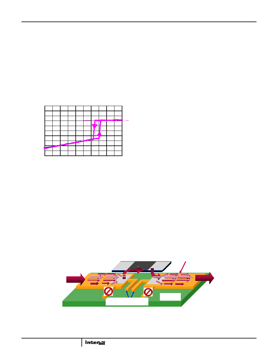
Layout Guidelines
The Kelvin Connected Sense Resistor
The source of Kelvin voltage errors is illustrated in Figure 79. The
resistance of 1/2 Oz copper is ~1m per square with a TC of
~3900ppm/°C (0.39%/°C). When you compare this unwanted
parasitic resistance with the total 1m to 10m resistance of
the sense resistor, it is easy to see why the sense connection
must be chosen very carefully. For example, consider a
maximum current of 20A through a 0.005 sense resistor,
generating a VSENSE = 0.1 and a full scale output voltage of 10V
(G = 100). Two side contacts of only 0.25 square per contact puts
the VSENSE input about 0.5 x 1m away from the resistor end
capacitor. If only 10A the 20A total current flows through the
kelvin path to the resistor, you get an error voltage of 10mV
(10A x 0.5sq x 0.001/sq. = 10mV) added to the 100mV sense
voltage for a sense voltage error of 10% (0.110V-0.1)/0.1V) x 100.
FIGURE 78. GAIN ACCURACY vs VRS+ = 0V TO 2V
VRS+ (V)
-0.5
-0.4
-0.3
-0.2
-0.1
0
0.1
0.2
0.3
0.4
0.5
0
0.2 0.4 0.6 0.81.0 1.21.4 1.61.8 2.0
ACCURACY
(%
)
(EQ. 3)
RP IRS-
×
()
100
Ω 130nA
×
()
13
μV
==
()
FIGURE 79. PC BOARD CURRENT SENSE KELVIN CONNECTION
PC Board
Non-uniform
Current Flow
Current Sense Resistor
1 to 10mO
Current In
Current Out
Kelvin V
S Contacts
Copper Trace
30mO/Sq.
PC Board
Non-uniform
Current Flow
Current Sense Resistor
1 to 10mO
Current In
Current Out
Kelvin V
S Contacts
Copper Trace
30mO/Sq.
CURRENT SENSE RESISTOR
1m TO 10m
1m /SQ
CURRENT OUT
CURRENT IN
NON-UNIFORM
CURRENT FLOW
PC BOARD
KELVIN VS CONTACTS
1/2 Oz COPPER TRACE
相关PDF资料 |
PDF描述 |
|---|---|
| ISL28107FBZ | IC OPAMP GP 1MHZ LN 8SOIC |
| ISL28108FRTZ-T7 | IC OPAMP GP RR 1.2MHZ 8TDFN |
| ISL28118FBZ-T7A | IC OPAMP PREC R-R 4MHZ LP 8SOIC |
| ISL28118MUZ-T7A | IC OPAMP PREC R-R 4MHZ LP 8MSOP |
| ISL28127FBZ | IC OPAMP LN SGL 10MHZ 8-SOIC |
相关代理商/技术参数 |
参数描述 |
|---|---|
| ISL28006FHADJZ-T7A | 功能描述:放大器 IC 开发工具 ISL28006FHADJZ MICRO PWR CUR SENSE AMP W/ RoHS:否 制造商:International Rectifier 产品:Demonstration Boards 类型:Power Amplifiers 工具用于评估:IR4302 工作电源电压:13 V to 23 V |
| ISL28022 | 制造商:INTERSIL 制造商全称:Intersil Corporation 功能描述:Precision Digital Power Monitor |
| ISL28022EV1Z | 制造商:Intersil Corporation 功能描述:EVAL BOARD FOR ISL28022 制造商:Intersil Corporation 功能描述:EVALUATION BOARD 1 - 10 Ld MSOP - RoHS COMPLIANT |
| ISL28022FRZ | 制造商:INTERSIL 制造商全称:Intersil Corporation 功能描述:Precision Digital Power Monitor |
| ISL28022FRZR5453 | 制造商:INTERSIL 制造商全称:Intersil Corporation 功能描述:Precision Digital Power Monitor |
发布紧急采购,3分钟左右您将得到回复。