参数资料
| 型号: | ISL28195FHZ-T7 |
| 厂商: | Intersil |
| 文件页数: | 2/12页 |
| 文件大小: | 0K |
| 描述: | IC OPAMP RRIO 1UA SOT23-6 |
| 标准包装: | 1 |
| 放大器类型: | 通用 |
| 电路数: | 1 |
| 输出类型: | 满摆幅 |
| 转换速率: | 0.0042 V/µs |
| 增益带宽积: | 10kHz |
| 电流 - 输入偏压: | 15pA |
| 电压 - 输入偏移: | 100µV |
| 电流 - 电源: | 1µA |
| 电流 - 输出 / 通道: | 12mA |
| 电压 - 电源,单路/双路(±): | 1.8 V ~ 5.5 V,±0.9 V ~ 2.75 V |
| 工作温度: | -40°C ~ 125°C |
| 安装类型: | 表面贴装 |
| 封装/外壳: | SOT-23-6 |
| 供应商设备封装: | SOT-23-6 |
| 包装: | 标准包装 |
| 产品目录页面: | 1234 (CN2011-ZH PDF) |
| 其它名称: | ISL28195FHZ-T7DKR |
10
FN6236.5
January 14, 2014
Intersil products are manufactured, assembled and tested utilizing ISO9001 quality systems as noted
in the quality certifications found at www.intersil.com/en/support/qualandreliability.html
Intersil products are sold by description only. Intersil Corporation reserves the right to make changes in circuit design, software and/or specifications at any time
without notice. Accordingly, the reader is cautioned to verify that data sheets are current before placing orders. Information furnished by Intersil is believed to be
accurate and reliable. However, no responsibility is assumed by Intersil or its subsidiaries for its use; nor for any infringements of patents or other rights of third
parties which may result from its use. No license is granted by implication or otherwise under any patent or patent rights of Intersil or its subsidiaries.
For information regarding Intersil Corporation and its products, see www.intersil.com
For additional products, see www.intersil.com/en/products.html
In the disabled state (output in a high impedance state), the
supply current is reduced to typical of only 2nA. By disabling
the devices, multiple parts can be connected together as a
MUX. In this configuration, the outputs are tied together in
parallel and a channel can be selected by the EN pin. The
EN pin should never be left floating. The EN pin should be
connected directly to the V+ supply when not in use.
The loading effects of the feedback resistors of the disabled
amplifier must be considered when multiple amplifier outputs
are connected together.
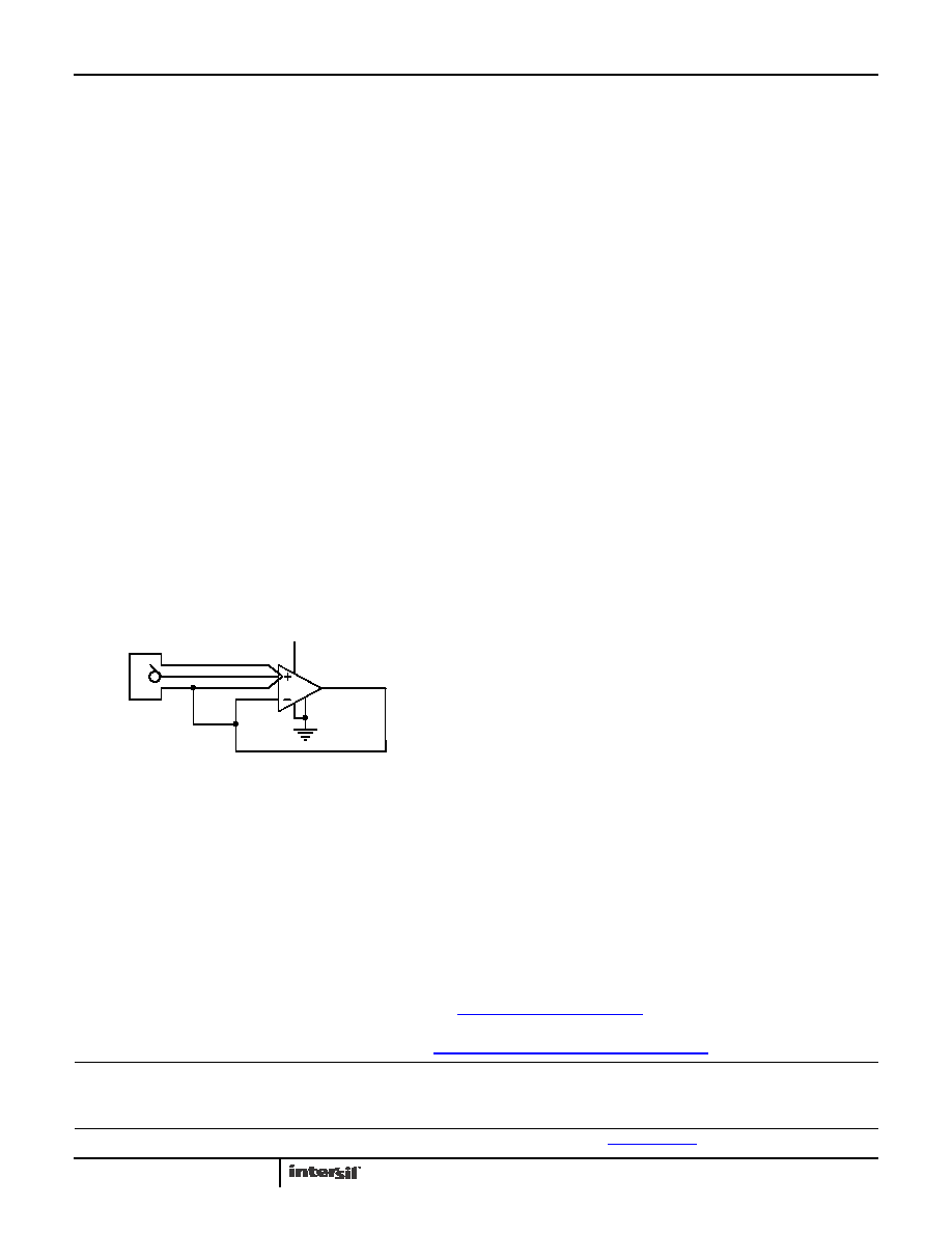
Proper Layout Maximizes Performance
To achieve the maximum performance of the high input
impedance, care should be taken in the circuit board layout.
The PC board surface must remain clean and free of moisture
to avoid leakage currents between adjacent traces. Surface
coating of the circuit board will reduce surface moisture and
provide a humidity barrier, reducing parasitic resistance on the
board. When input leakage current is a concern, the use of
guard rings around the amplifier inputs will further reduce
leakage currents. Figure 30 shows a guard ring example for a
unity gain amplifier that uses the low impedance amplifier
output at the same voltage as the high impedance input to
eliminate surface leakage. The guard ring does not need to be
a specific width, but it should form a continuous loop around
both inputs. For further reduction of leakage currents,
components can be mounted to the PC board using Teflon
standoff insulators.
Power Dissipation
It is possible to exceed the +150°C maximum junction
temperatures under certain load and power-supply
conditions. It is therefore important to calculate the
maximum junction temperature (TJMAX) for all applications
to determine if power supply voltages, load conditions, or
package type need to be modified to remain in the safe
operating area. These parameters are related in Equation 1:
where:
PDMAXTOTAL is the sum of the maximum power
dissipation of each amplifier in the package (PDMAX)
PDMAX for each amplifier can be calculated as shown in
Equation 2:
where:
TMAX = Maximum ambient temperature
θJA = Thermal resistance of the package
PDMAX = Maximum power dissipation of 1 amplifier
VS = Supply voltage (Magnitude of V+ and V-)
IMAX = Maximum supply current of 1 amplifier
VOUTMAX = Maximum output voltage swing of the
application
RL = Load resistance
IN
V+
FIGURE 30. GUARD RING EXAMPLE FOR UNITY GAIN
AMPLIFIER
HIGH IMPEDANCE INPUT
T
JMAX
T
MAX
θ
JAxPDMAXTOTAL
()
+
=
(EQ. 1)
PD
MAX
2*V
S
I
SMAX
V
S
(
- V
OUTMAX )
V
OUTMAX
R
L
----------------------------
×
+
×
=
(EQ. 2)
ISL28194
相关PDF资料 |
PDF描述 |
|---|---|
| AD8557ACPZ-REEL | IC AMP CHOPPER 2MHZ 55MA 16LFCSP |
| ADA4091-2ACPZ-RL | IC OPAMP GP R-R 1.27MHZ 8LFCSP |
| AD706JRZ-REEL | IC OPAMP GP DUAL PREC 15MA 8SOIC |
| LTC6247ITS8#TRMPBF | IC OPAMP RRIO 180MHZ DL TSOT23-8 |
| LTC6247IKC#TRMPBF | IC OPAMP RRIO 180MHZ DL 8UTDFN |
相关代理商/技术参数 |
参数描述 |
|---|---|
| ISL28195FHZ-T7A | 功能描述:运算放大器 - 运放 ISL28195FHZ ULTRA SMALL 1A SNGL SUPPLY RoHS:否 制造商:STMicroelectronics 通道数量:4 共模抑制比(最小值):63 dB 输入补偿电压:1 mV 输入偏流(最大值):10 pA 工作电源电压:2.7 V to 5.5 V 安装风格:SMD/SMT 封装 / 箱体:QFN-16 转换速度:0.89 V/us 关闭:No 输出电流:55 mA 最大工作温度:+ 125 C 封装:Reel |
| ISL28195FRUZ-T7 | 功能描述:IC OPAMP RRIO SGL 1UA 6-TDFN RoHS:是 类别:集成电路 (IC) >> Linear - Amplifiers - Instrumentation 系列:- 其它有关文件:Automotive Product Guide 产品培训模块:Lead (SnPb) Finish for COTS Obsolescence Mitigation Program 标准包装:1 系列:- 放大器类型:通用 电路数:1 输出类型:满摆幅 转换速率:3 V/µs 增益带宽积:10MHz -3db带宽:- 电流 - 输入偏压:1pA 电压 - 输入偏移:70µV 电流 - 电源:2.5mA 电流 - 输出 / 通道:48mA 电压 - 电源,单路/双路(±):2.7 V ~ 5.5 V,±1.35 V ~ 2.75 V 工作温度:-40°C ~ 125°C 安装类型:表面贴装 封装/外壳:SOT-23-6 供应商设备封装:SOT-6 包装:Digi-Reel® 其它名称:MAX4475AUT#TG16DKR |
| ISL28196 | 制造商:INTERSIL 制造商全称:Intersil Corporation 功能描述:Ultra-Small, 800nA and 2.5μA Single Supply, Rail-to-Rail Input/Output RRIO Comparators |
| ISL28196 WAF | 制造商:Intersil Corporation 功能描述: |
| ISL28196EVAL1Z | 功能描述:EVALUATION BOARD FOR ISL28196 RoHS:是 类别:编程器,开发系统 >> 评估演示板和套件 系列:- 产品培训模块:Obsolescence Mitigation Program 标准包装:1 系列:- 主要目的:电源管理,电池充电器 嵌入式:否 已用 IC / 零件:MAX8903A 主要属性:1 芯锂离子电池 次要属性:状态 LED 已供物品:板 |
发布紧急采购,3分钟左右您将得到回复。