参数资料
| 型号: | ISL28278FAZ |
| 厂商: | Intersil |
| 文件页数: | 5/16页 |
| 文件大小: | 0K |
| 描述: | IC OPAMP DUAL RRIO PREC 16-QSOP |
| 标准包装: | 97 |
| 放大器类型: | 通用 |
| 电路数: | 2 |
| 输出类型: | 满摆幅 |
| 转换速率: | 0.14 V/µs |
| 增益带宽积: | 300kHz |
| 电流 - 输入偏压: | 10pA |
| 电压 - 输入偏移: | 0.2µV |
| 电流 - 电源: | 120µA |
| 电流 - 输出 / 通道: | 31mA |
| 电压 - 电源,单路/双路(±): | 2.4 V ~ 5.5 V,±1.2 V ~ 2.75 V |
| 工作温度: | -40°C ~ 125°C |
| 安装类型: | 表面贴装 |
| 封装/外壳: | 16-SSOP(0.154",3.90mm 宽) |
| 供应商设备封装: | 16-QSOP |
| 包装: | 管件 |
| 产品目录页面: | 1235 (CN2011-ZH PDF) |
ISL28278, ISL28478
13
FN6145.4
August 16, 2011
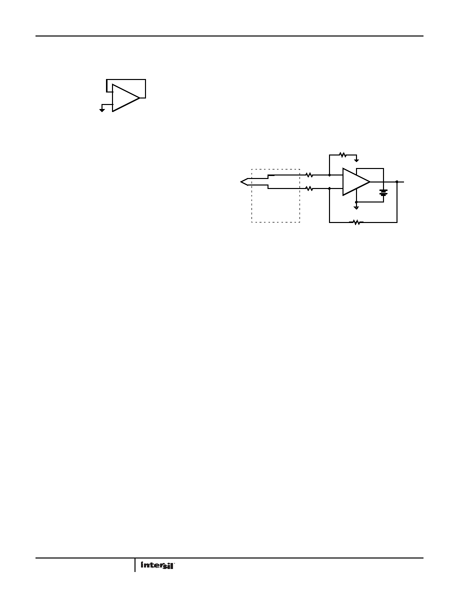
expected supply currents and possible noise injection into the
channel being used. The proper way to prevent this oscillation is
to short the output to the negative input, and ground the positive
input (as shown in Figure 40).
Proper Layout Maximizes Performance
To achieve maximum performance from the high input
impedance and low offset voltage of the ISL28278 and
ISL28478, care should be taken in circuit board layout. The PC
board surface must remain clean and free of moisture to avoid
leakage currents between adjacent traces. Surface coating of the
circuit board reduces surface moisture and provides a humidity
barrier, reducing parasitic resistance on the board.
Current Limiting
The ISL28278 and ISL28478 have no internal current-limiting
circuitry. If the output is shorted, it is possible to exceed the
absolute maximum rating for output current or power
dissipation, potentially resulting in destruction of the device.
Power Dissipation
It is possible to exceed the +150°C maximum junction
temperatures under certain load and power-supply conditions. It
is therefore important to calculate the maximum junction
temperature (TJMAX) for all applications, to determine whether
power supply voltages, load conditions, or package type need to
be modified to remain in the safe operating area. These
parameters are related in Equation 1:
where:
TMAX = Maximum ambient temperature
θJA = Thermal resistance of the package
PDMAXTOTAL is the sum of the maximum power dissipation of
each amplifier in the package (PDMAX)
where:
PDMAX = Maximum power dissipation of one amplifier
VS = Supply voltage (magnitude of V+ and V-)
ISMAX = Maximum supply current of one amplifier
VOUTMAX = Maximum output voltage swing of the application
RL = Load resistance
Application Circuits
THERMOCOUPLE AMPLIFIER
Thermocouples are the most popular temperature-sensing
device because of their low cost, interchangeability, and ability to
measure a wide range of temperatures. The ISL28x78 (see
Figure 41) is used to convert the differential thermocouple
voltage into a single-ended signal with 10x gain. The amplifier’s
rail-to-rail input characteristic allows the thermocouple to be
biased at ground and the amplifier to run from a single 5V
supply.
ECG AMPLIFIER
In medical applications, ECG amplifiers must extract millivolt low
frequency AC signals from the skin of the patient while rejecting
AC common mode interference and static DC potentials created
at the electrode-to-skin interface. In Figure 42, the ISL28278
(U1) forms one of the multiple high gain AC band-pass amplifiers
using active feedback. Amplifier U1B and RC RF1, CF1 form a
high gain LP filtered amplifier with the corner frequency given by
Equation 3:
Inserting the low pass amplifier, U1B, in the U1A feedback loop
results in an overall high-pass frequency response. Voltage
divider pairs R1-R2 and R3-R4 set the overall amplifier pass-band
gain. The DC input offset is canceled by U1B at the U1A inverting
input. Resistor divider pair R3-R4 defines the maximum input DC
level that is canceled, and is given by Equation 4:
In the passband range, U1B gain is +1, and the total signal gain
is defined by the divider ratios according to Equation 5:
At frequencies greater than the LPF corner, the R1-C1 and R3-C3
networks work to roll-off the U1A gain to unity. Setting both R-C
time constants to the same value simplifies to Equation 6:
Right leg drive and reference amplifiers U2A and U2B form a DC
feedback loop that applies a correction voltage at the right leg
FIGURE 40. PREVENTING OSCILLATIONS IN UNUSED CHANNELS
-
+
1/2 ISL28278
1/4 ISL28478
TJMAX
TMAX θJAxPDMAXTOTAL
()
+
=
(EQ. 1)
PDMAX
2*VS ISMAX VS
(
- VOUTMAX)
VOUTMAX
RL
------------------------
×
+
×
=
(EQ. 2)
-
+
5V
+
V+
V-
ISL28x78
10k
R3
10k
R2
R4
100k
R1
100k
410V/°C
FIGURE 41. THERMOCOUPLE AMPLIFIER
COLD JUNCTION
COMPENSATION
K TYPE
THERMOCOUPLE
f-HPF-3dB
1
2Pi
×
RF1
×
CF1
×
--------------------------------------------------
=
(EQ. 3)
VINDC
V+
R4
R3 R4
+
--------------------
×
=
(EQ. 4)
VOUTU1 GAIN
VOUT
VIN
-------------
R1 R2
+
R2
--------------------
R3 R4
+
R4
--------------------
×
=
(EQ. 5)
f-LPF-3dB
1
2Pi
×
R1
×
C1
×
-----------------------------------------
=
(EQ. 6)
相关PDF资料 |
PDF描述 |
|---|---|
| 5-147727-5 | 06 MODIV VRT SR OUTRIGGER SN |
| 1-215079-6 | CONN FMALE-ON-BRD 16POS VERT T/H |
| LT1399CGN#TRPBF | IC CRRNT FEEDBK AMP TRPL 16-SSOP |
| ISL55290IUZ-T13 | IC OPAMP LP DUAL ULT LN 10-MSOP |
| LTC2051IMS10#TRPBF | IC OPAMP ZERO DRIFT DUAL 10MSOP |
相关代理商/技术参数 |
参数描述 |
|---|---|
| ISL28278FAZ-T7 | 功能描述:IC OPAMP DUAL RRIO PREC 16-QSOP RoHS:是 类别:集成电路 (IC) >> Linear - Amplifiers - Instrumentation 系列:- 其它有关文件:Automotive Product Guide 产品培训模块:Lead (SnPb) Finish for COTS Obsolescence Mitigation Program 标准包装:1 系列:- 放大器类型:通用 电路数:1 输出类型:满摆幅 转换速率:3 V/µs 增益带宽积:10MHz -3db带宽:- 电流 - 输入偏压:1pA 电压 - 输入偏移:70µV 电流 - 电源:2.5mA 电流 - 输出 / 通道:48mA 电压 - 电源,单路/双路(±):2.7 V ~ 5.5 V,±1.35 V ~ 2.75 V 工作温度:-40°C ~ 125°C 安装类型:表面贴装 封装/外壳:SOT-23-6 供应商设备封装:SOT-6 包装:Digi-Reel® 其它名称:MAX4475AUT#TG16DKR |
| ISL28278FAZ-TZ | 制造商:Rochester Electronics LLC 功能描述: 制造商:Intersil Corporation 功能描述: |
| ISL28286 | 制造商:INTERSIL 制造商全称:Intersil Corporation 功能描述:Dual and Quad Micropower Single Supply Dual and Quad Micropower Single Supply Precision Op Amp |
| ISL28286_07 | 制造商:INTERSIL 制造商全称:Intersil Corporation 功能描述:Dual and Quad Micropower Single Supply Dual and Quad Micropower Single Supply Precision Op Amp |
| ISL28286EVAL1Z | 功能描述:EVALUATION BOARD FOR ISL28286 RoHS:是 类别:编程器,开发系统 >> 评估板 - 运算放大器 系列:- 产品培训模块:Lead (SnPb) Finish for COTS Obsolescence Mitigation Program 标准包装:1 系列:- |
发布紧急采购,3分钟左右您将得到回复。