- 您现在的位置:买卖IC网 > PDF目录10689 > ISL31485EIBZ-T7A (Intersil)IC TXRX RS485 FAULT PROT 8SOIC PDF资料下载
参数资料
| 型号: | ISL31485EIBZ-T7A |
| 厂商: | Intersil |
| 文件页数: | 8/24页 |
| 文件大小: | 0K |
| 描述: | IC TXRX RS485 FAULT PROT 8SOIC |
| 标准包装: | 1 |
| 类型: | 收发器 |
| 驱动器/接收器数: | 1/1 |
| 规程: | RS422,RS485 |
| 电源电压: | 4.5 V ~ 5.5 V |
| 安装类型: | 表面贴装 |
| 封装/外壳: | 8-SOIC(0.154",3.90mm 宽) |
| 供应商设备封装: | 8-SOICN |
| 包装: | 标准包装 |
| 其它名称: | ISL31485EIBZ-T7ADKR |
ISL31480E, ISL31483E, ISL31485E, ISL31486E
16
FN7638.2
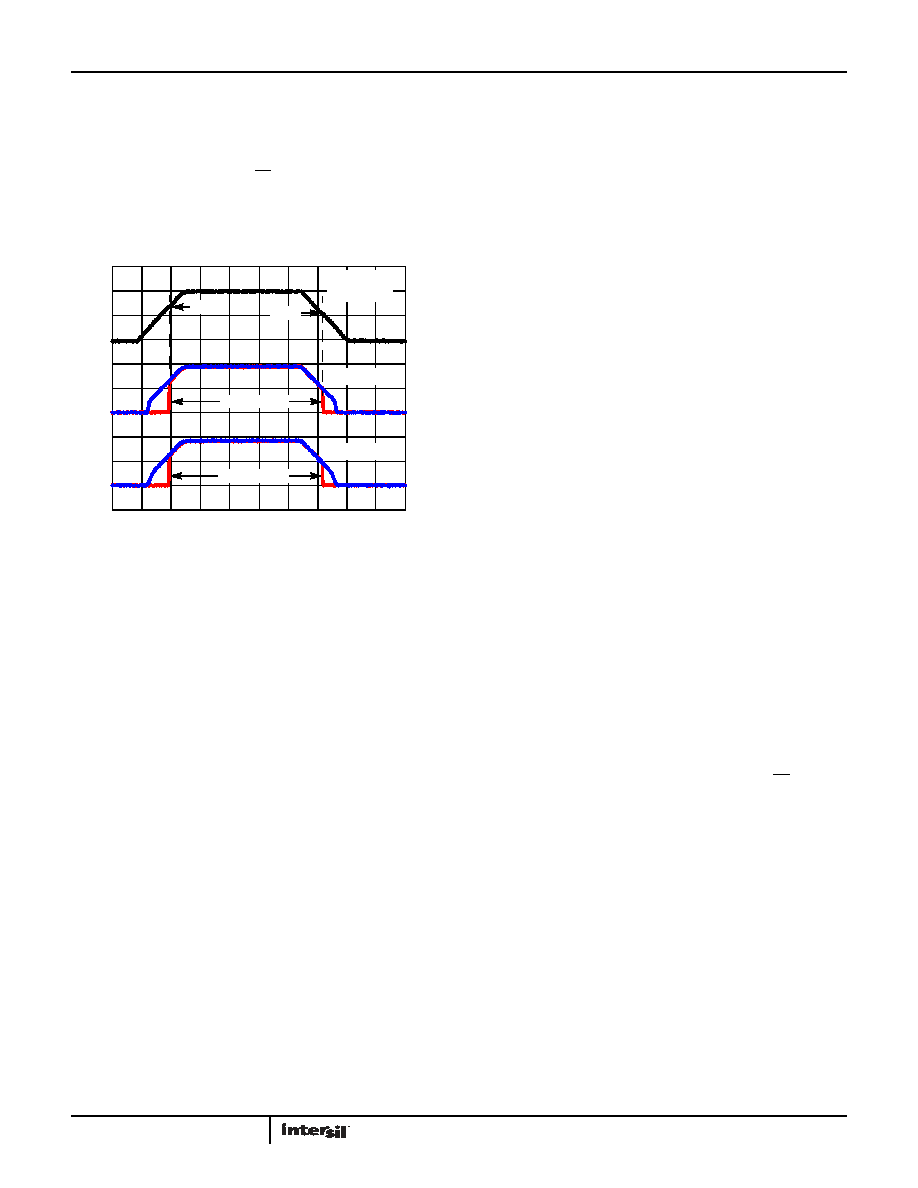
kept disabled. If the equipment is connected to the bus, a driver
activating prematurely during power-up may crash the bus. To
avoid this scenario, the ISL3148xE devices incorporate a “Hot
Plug” function. Circuitry monitoring VCC ensures that, during power-
up and power-down, the Tx and Rx outputs remain disabled,
regardless of the state of DE and RE, if VCC is less than ≈3.5V. This
gives the processor/ASIC a chance to stabilize and drive the RS-485
control lines to the proper states. Figure 10 illustrates the power-up
and power-down performance of the ISL3148xE compared to an RS-
485 IC without the Hot Plug feature.
Data Rate, Cables, and Terminations
RS-485/RS-422 are intended for network lengths up to 4000’,
but the maximum system data rate decreases as the
transmission length increases. These 1Mbps versions can
operate at full data rates with lengths up to 800’ (244m). Jitter is
the limiting parameter at this data rate, so employing encoded
data streams (e.g., Manchester coded or Return-to-Zero) may
allow increased transmission distances.
Twisted pair is the cable of choice for RS-485/RS-422 networks.
Twisted pair cables tend to pick up noise and other
electromagnetically induced voltages as common mode signals,
which are effectively rejected by the differential receivers in
these ICs.
Proper termination is imperative to minimize reflections, and
terminations are recommended unless power dissipation is an
overriding concern. In point-to-point, or point-to-multipoint (single
driver on bus like RS-422) networks, the main cable should be
terminated in its characteristic impedance (typically 120) at the
end farthest from the driver. In multi-receiver applications, stubs
connecting receivers to the main cable should be kept as short
as possible. Multipoint (multi-driver) systems require that the
main cable be terminated in its characteristic impedance at both
ends. Stubs connecting a transceiver to the main cable should be
kept as short as possible.
Built-In Driver Overload Protection
As stated previously, the RS-485 specification requires that
drivers survive worst case bus contentions undamaged. These
transceivers meet this requirement via driver output short circuit
current limits, and on-chip thermal shutdown circuitry.
The driver output stages incorporate a double foldback short
circuit current limiting scheme which ensures that the output
current never exceeds the RS-485 specification, even at the
common mode and fault condition voltage range extremes. The
first foldback current level (≈70mA) is set to ensure that the
driver never folds back when driving loads with common mode
voltages up to ±25V. The very low second foldback current
setting (≈9mA) minimizes power dissipation if the Tx is enabled
when a fault occurs.
In the event of a major short circuit condition, devices also include
a thermal shutdown feature that disables the drivers whenever the
die temperature becomes excessive. This eliminates the power
dissipation, allowing the die to cool. The drivers automatically
re-enable after the die temperature drops about 15°C. If the
contention persists, the thermal shutdown/re-enable cycle repeats
until the fault is cleared. Receivers stay operational during thermal
shutdown.
Low Power Shutdown Mode
These CMOS transceivers all use a fraction of the power required
by competitive devices, but they also include a shutdown feature
(except the ISL31485E) that reduces the already low quiescent
ICC to a 10A trickle. These devices enter shutdown whenever
the receiver and driver are simultaneously disabled (RE =VCC
and DE = GND) for a period of at least 600ns. Disabling both the
driver and the receiver for less than 60ns guarantees that the
transceiver will not enter shutdown.
Note that receiver and driver enable times increase when the
transceiver enables from shutdown. Refer to Notes 11, 12, 13,
page 11, for more information.
FIGURE 10. HOT PLUG PERFORMANCE ISL3148XE vs
ISL83088E WITHOUT HOT PLUG CIRCUITRY
TIME (40s/DIV)
VCC
R
E
CEIVER
OUTPUT
(V
)
DRI
VER
Y
OUTPUT
(V
)
2.5
5.0
2.5
5.0
V
CC
(V
)
RL = 1k
RO
0
2.5
5.0
0
A/Y
RL = 1k
3.5V
RE = GND
DE, DI = VCC
2.8V
ISL3148XE
相关PDF资料 |
PDF描述 |
|---|---|
| LTC1445CN | IC COMP W/REF LOWPWR QUAD 16-DIP |
| LTC2488IDE#PBF | IC ADC 16BIT DELTA SIG 14-DFN |
| LTC1443CN#PBF | IC COMP W/REF LOWPWR QUAD 16-DIP |
| LTC1443CN | IC COMP W/REF LOWPWR QUAD 16-DIP |
| LTC2489IDE#PBF | IC ADC 16BIT DELTA SIG 14-DFN |
相关代理商/技术参数 |
参数描述 |
|---|---|
| ISL31486E | 制造商:INTERSIL 制造商全称:Intersil Corporation 功能描述:Fault Protected, Extended CMR, RS-485/RS-422 Transceivers with Cable Invert |
| ISL31486EIBZ | 制造商:INTERSIL 制造商全称:Intersil Corporation 功能描述:Fault Protected, Extended CMR, RS-485/RS-422 Transceivers with Cable Invert |
| ISL31486EIRTZ | 制造商:INTERSIL 制造商全称:Intersil Corporation 功能描述:Fault Protected, Extended CMR, RS-485/RS-422 Transceivers with Cable Invert |
| ISL31486EIUZ | 制造商:INTERSIL 制造商全称:Intersil Corporation 功能描述:Fault Protected, Extended CMR, RS-485/RS-422 Transceivers with Cable Invert |
| ISL31490E | 制造商:INTERSIL 制造商全称:Intersil Corporation 功能描述:?±60V Fault Protected, 5V, RS-485/RS-422 Transceivers with ?±25V Common Mode Range |
发布紧急采购,3分钟左右您将得到回复。