- 您现在的位置:买卖IC网 > PDF目录383135 > ISL5585CIM (INTERSIL CORP) 3.3V Ringing SLIC Family for Voice Over Broadband VOB PDF资料下载
参数资料
| 型号: | ISL5585CIM |
| 厂商: | INTERSIL CORP |
| 元件分类: | 模拟传输电路 |
| 英文描述: | 3.3V Ringing SLIC Family for Voice Over Broadband VOB |
| 中文描述: | TELECOM-SLIC, PQCC28 |
| 封装: | PLASTIC, MS-018AB, LCC-28 |
| 文件页数: | 9/22页 |
| 文件大小: | 425K |
| 代理商: | ISL5585CIM |
9
detection of ring trip or programmed off hook loop current,
whichever is greater.
To allow for proper ring trip operation, the transient current
limit setting should be set at least 25% higher than the peak
ring trip current setting. Setting the transient current 25%
higher should account for programming tolerances of both
the ring trip threshold and the transient current limit.
If loop current is larger than ring trip current (low REN
applications) then the transient current limit should be set at
least 35% higher than the loop current setting. The slightly
higher offset accounts for the slope of the loop current limit
function.
Attention to detail should be exercised when programming
the transient current limit setting. If ring trip detect does not
occur while ringing, then re-examine the transient current
limit and ring trip threshold settings.
DC Loop Feed
The feedback mechanism for monitoring the DC portion of
the loop current is the loop detector. A low pass filter is used
in the feedback to block voice band signals from interfering
with the loop current limit function. The pole of the low pass
filter is set by the external capacitor C
DC
. The value of the
external capacitor should be 4.7
μ
F, 6.3V rated polarized or
non-polarized capacitor.
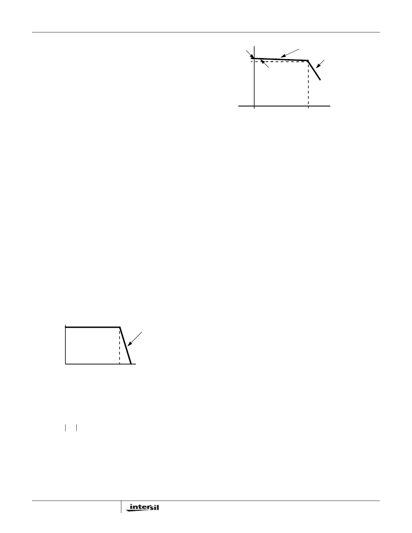
Most applications will operate the device from low battery
while off hook. The DC feed characteristic of the device will
drive Tip and Ring towards half battery to regulate the DC
loop current. For light loads or Long Loops, Tip will be near
-4V and Ring will be near V
VBL
+ 5V. Figure 2 shows the DC
feed characteristic in terms of tip to ring voltage and loop
current.
The point on the y-axis labeled V
TR(OC)
is the open circuit
Tip to Ring voltage and is defined by the feed battery voltage
in Equation 6.
Figure 3 illustrates the actual loop current for a given set of
loop conditions. The loop conditions are determined by the
low battery voltage and the DC loop impedance. The DC
loop impedance is the sum of the protection resistance,
copper resistance (ohms/foot) and the telephone off hook
DC resistance.
The slope of the feed characteristic and the battery voltage
define the maximum loop current on the shortest possible
loop as the short circuit current I
SC
.
V
–
The term I
LIM
is the programmed current limit, 1760/R
IL
. The
line segment I
A
represents the constant current region of the
loop current limit function.
Process variations in the ISL5585 effect the I
LIM
and
11.11k
slope in Equation 8. All units are tested with: a
300
load across tip and ring, V
BAT
=-24V and I
LIM
set to
25mA. Equation 8 can be used to predict the ideal current at
this setting (25.76mA). All units are tested to be within
±8.5% of this ideal value (23.57mA to 27.95mA).
The maximum loop impedance for a programmed loop
current is defined as R
KNEE
.
V
)
LIM
When R
KNEE
is exceeded, the device will transition from
constant current feed to constant voltage or resistive feed.
The line segment I
B
represents the resistive feed portion of
the load characteristic
V
)
LOOP
Impedance Matching
The impedance of the device is programmed with the
external component R
S
. R
S
is the gain setting resistor for
the Transmit Amplifier that provides impedance matching. If
complex impedance matching is required, then a complex
network can be substituted for R
S
.
The feedback mechanism for monitoring the AC portion of
the loop current consists of two amplifiers, the Sense
Amplifier (SA) and the Transmit Amplifier (TA). The AC
feedback signal is used for impedance synthesis. A detailed
model of the AC feed back loop is shown in Figure 4.
FIGURE 2. DC FEED CHARACTERISTIC
m = (
V
TR
/
I
L
) = 11.1k
I
LOOP
(mA)
I
LIM
V
TR(OC)
V
T
,
LONG LOOP
SHORT LOOP
V
TR OC
)
V
BL
9
–
=
(EQ. 6)
FIGURE 3. I
LOOP
vs. R
LOOP
LOAD CHARACTERISTIC
R
LOOP
(
)
R
KNEE
I
LIM
I
L
I
SC
I
A
I
B
m=Vtr(oc)/Rloop
2R
P
LONG LOOP
SHORT LOOP
m=11.11k
CONSTANT CURRENT
CONSTANT VOLTAGE
OR
RESISTIVE FEED
I
SC
I
LIM
2R
I
-----------------------------------------------------
+
=
(EQ. 7)
I
A
I
LIM
V
--------------------------------------------------------------
R
I
–
+
=
(EQ. 8)
R
KNEE
-----------------------
=
(EQ. 9)
I
B
-----------------------
=
(EQ. 10)
ISL5585
相关PDF资料 |
PDF描述 |
|---|---|
| ISL5585AIM | 3.3V Ringing SLIC Family for Voice Over Broadband VOB |
| ISL5585DIM | 3.3V Ringing SLIC Family for Voice Over Broadband VOB |
| ISL5585ECM | 3.3V Ringing SLIC Family for Voice Over Broadband VOB |
| ISL5585ECR | 3.3V Ringing SLIC Family for Voice Over Broadband VOB |
| ISL5585GCM | CONNECTOR ACCESSORY |
相关代理商/技术参数 |
参数描述 |
|---|---|
| ISL5585CIMZ | 制造商:Intersil Corporation 功能描述:SLIC 1CH 64DB 45MA 3.3V/-18V/-24V/-28V 28PLCC - Rail/Tube 制造商:Intersil 功能描述:RINGING SLIC W/3 3V VCC 100V/53DB |
| ISL5585CIMZ-T | 制造商:Intersil Corporation 功能描述:SLIC 1CH 64DB 45MA 3.3V/-18V/-24V/-28V 28PLCC - Tape and Reel 制造商:Intersil 功能描述:RINGING SLIC W/3 3V VCC 100V/53DB |
| ISL5585DIM | 制造商:INTERSIL 制造商全称:Intersil Corporation 功能描述:3.3V Ringing SLIC Family for Voice Over Broadband (VOB) |
| ISL5585DIMZ | 制造商:Intersil Corporation 功能描述:SLIC 1CH 64DB 45MA 3.3V/-18V/-24V/-28V 28PLCC - Rail/Tube 制造商:Intersil Corporation 功能描述:Telecom Line Management ICs RINGING SLIC W/3 3V VCC 85V/53DB |
| ISL5585DIMZ-T | 制造商:Intersil Corporation 功能描述:SLIC 1CH 64DB 45MA 3.3V/-18V/-24V/-28V 28PLCC - Tape and Reel 制造商:Intersil Corporation 功能描述:Telecom Line Management ICs RINGING SLIC W/3 3V VCC 85V/53DB |
发布紧急采购,3分钟左右您将得到回复。