- 您现在的位置:买卖IC网 > PDF目录10837 > ISL59444IB-T13 (Intersil)IC CROSSPOINT SW 1GHZ 4X1 16SOIC PDF资料下载
参数资料
| 型号: | ISL59444IB-T13 |
| 厂商: | Intersil |
| 文件页数: | 3/12页 |
| 文件大小: | 0K |
| 描述: | IC CROSSPOINT SW 1GHZ 4X1 16SOIC |
| 标准包装: | 2,500 |
| 应用: | 4:1 多路复用器-放大器 |
| 电路数: | 1 |
| -3db带宽: | 1GHz |
| 转换速率: | 1515 V/µs |
| 电流 - 电源: | 18mA |
| 电流 - 输出 / 通道: | 180mA |
| 电压 - 电源,单路/双路(±): | ±4.5 V ~ 5.5 V |
| 安装类型: | 表面贴装 |
| 封装/外壳: | 16-SOIC(0.154",3.90mm 宽) |
| 供应商设备封装: | 16-SOIC |
| 包装: | 带卷 (TR) |
ISL59444
11
Intersil products are manufactured, assembled and tested utilizing ISO9000 quality systems as noted
in the quality certifications found at www.intersil.com/design/quality
Intersil products are sold by description only. Intersil Corporation reserves the right to make changes in circuit design, software and/or specifications at any time
without notice. Accordingly, the reader is cautioned to verify that data sheets are current before placing orders. Information furnished by Intersil is believed to be
accurate and reliable. However, no responsibility is assumed by Intersil or its subsidiaries for its use; nor for any infringements of patents or other rights of third
parties which may result from its use. No license is granted by implication or otherwise under any patent or patent rights of Intersil or its subsidiaries.
For information regarding Intersil Corporation and its products, see www.intersil.com
FN7451.3
August 16, 2012
For additional products, see www.intersil.com/product_tree
Power-Up Considerations
The ESD protection circuits use internal diodes from all pins the
V+ and V- supplies. In addition, a dv/dt triggered clamp is
connected between the V+ and V- pins, as shown in the
Equivalent Circuits 1 through 4 section of the “Pin Descriptions”
on page 2. The dv/dt triggered clamp imposes a maximum
supply turn-on slew rate of 1V/s. Damaging currents can flow
for power supply rates-of-rise in excess of 1V/s, such as during
hot plugging. Under these conditions, additional methods should
be employed to ensure the rate of rise is not exceeded.
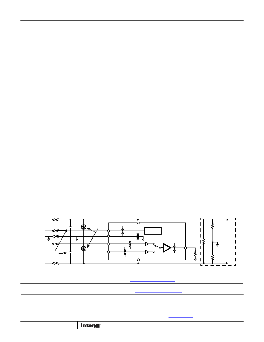
Consideration must be given to the order in which power is
applied to the V+ and V- pins, as well as analog and logic input
pins. Schottky diodes (Motorola MBR0550T or equivalent)
connected from V+ to ground and V- to ground (Figure 25) will
shunt damaging currents away from the internal V+ and V- ESD
diodes in the event that the V+ supply is applied to the device
before the V- supply.
If positive voltages are applied to the logic or analog video input
pins before V+ is applied, current will flow through the internal
ESD diodes to the V+ pin. The presence of large decoupling
capacitors and the loading effect of other circuits connected to
V+, can result in damaging currents through the ESD diodes and
other active circuits within the device. Therefore, adequate
current limiting on the digital and analog inputs is needed to
prevent damage during the time the voltages on these inputs are
more positive than V+.
Limiting the Output Current
No output short circuit current limit exists on these parts. All
applications need to limit the output current to less than 50mA.
Adequate thermal heat sinking of the parts is also required.
PC Board Layout
The frequency response of this circuit depends greatly on the
care taken in designing the PC board. The following are
recommendations to achieve optimum high frequency
performance from your PC board.
The use of low inductance components such as chip resistors
and chip capacitors is strongly recommended.
Minimize signal trace lengths. Trace inductance and
capacitance can easily limit circuit performance. Avoid sharp
corners, use rounded corners when possible. Vias in the signal
lines add inductance at high frequency and should be avoided.
PCB traces greater than 1" begin to exhibit transmission line
characteristics with signal rise/fall times of 1ns or less. High
frequency performance may be degraded for traces greater
than one inch, unless strip lines are used.
Match channel-channel analog I/O trace lengths and layout
symmetry. This will minimize propagation delay mismatches.
Maximize use of AC de-coupled PCB layers. All signal I/O lines
should be routed over continuous ground planes (i.e., no split
planes or PCB gaps under these lines). Avoid vias in the signal
I/O lines.
Use proper value and location of termination resistors.
Termination resistors should be as close to the device as
possible.
When testing use good quality connectors and cables, matching
cable types and keeping cable lengths to a minimum.
Minimum of 2 power supply de-coupling capacitors are
recommended (1000pF, 0.01F) as close to the devices as
possible. Avoid vias between the cap and the device because
vias add unwanted inductance. Larger caps can be farther
away. When vias are required in a layout, they should be routed
as far away from the device as possible.
The NIC pins are placed on both sides of the input pins. These
pins are not internally connected to the die. It is recommended
these pins be tied to ground to minimize crosstalk.
V+
V-
V+
V-
V+
V-
LOGIC
CONTROL
GND
IN0
IN1
S0
OUT
EXTERNAL
CIRCUITS
SCHOTTKY
PROTECTION
V+
V-
POWER
GND
SIGNAL
LOGIC
V+ SUPPLY
V- SUPPLY
DE-COUPLING
CAPS
FIGURE 25. SCHOTTKY PROTECTION CIRCUIT
相关PDF资料 |
PDF描述 |
|---|---|
| ISL59442IB-T13 | IC CROSSPOINT SW 1GHZ 4X1 14SOIC |
| ISL59442IB | IC CROSSPOINT SW 1GHZ 4X1 14SOIC |
| MX7226KP+T | IC DAC 8BIT W/AMP 20-PLCC |
| MAX5151ACEE+ | IC DAC 13BIT DUAL LP SER 16-QSOP |
| MAX5150ACEE+ | IC DAC 13BIT DUAL LP SER 16-QSOP |
相关代理商/技术参数 |
参数描述 |
|---|---|
| ISL59444IB-T7 | 功能描述:IC CROSSPOINT SW 1GHZ 4X1 16SOIC RoHS:否 类别:集成电路 (IC) >> 线性 - 放大器 - 视频放大器和频缓冲器 系列:- 产品培训模块:Lead (SnPb) Finish for COTS Obsolescence Mitigation Program 标准包装:50 系列:- 应用:TFT-LCD 面板:VCOM 驱动器 输出类型:满摆幅 电路数:1 -3db带宽:35MHz 转换速率:40 V/µs 电流 - 电源:3.7mA 电流 - 输出 / 通道:1.3A 电压 - 电源,单路/双路(±):9 V ~ 20 V,±4.5 V ~ 10 V 安装类型:表面贴装 封装/外壳:8-TSSOP,8-MSOP(0.118",3.00mm 宽)裸露焊盘 供应商设备封装:8-uMax-EP 包装:管件 |
| ISL59444IBZ | 功能描述:IC CROSSPOINT SW 1GHZ 4X1 16SOIC RoHS:是 类别:集成电路 (IC) >> 线性 - 放大器 - 视频放大器和频缓冲器 系列:- 产品培训模块:Lead (SnPb) Finish for COTS Obsolescence Mitigation Program 标准包装:50 系列:- 应用:TFT-LCD 面板:VCOM 驱动器 输出类型:满摆幅 电路数:1 -3db带宽:35MHz 转换速率:40 V/µs 电流 - 电源:3.7mA 电流 - 输出 / 通道:1.3A 电压 - 电源,单路/双路(±):9 V ~ 20 V,±4.5 V ~ 10 V 安装类型:表面贴装 封装/外壳:8-TSSOP,8-MSOP(0.118",3.00mm 宽)裸露焊盘 供应商设备封装:8-uMax-EP 包装:管件 |
| ISL59444IBZ-T13 | 功能描述:IC AMP MULTIPLEX 1GHZ 16SOIC RoHS:是 类别:集成电路 (IC) >> 线性 - 放大器 - 视频放大器和频缓冲器 系列:- 标准包装:1,000 系列:- 应用:驱动器 输出类型:差分 电路数:3 -3db带宽:350MHz 转换速率:1000 V/µs 电流 - 电源:14.5mA 电流 - 输出 / 通道:60mA 电压 - 电源,单路/双路(±):5 V ~ 12 V,±2.5 V ~ 6 V 安装类型:表面贴装 封装/外壳:20-VFQFN 裸露焊盘 供应商设备封装:20-QFN 裸露焊盘(4x4) 包装:带卷 (TR) |
| ISL59444IBZ-T7 | 功能描述:IC AMP MULTIPLEX 1GHZ 16SOIC RoHS:是 类别:集成电路 (IC) >> 线性 - 放大器 - 视频放大器和频缓冲器 系列:- 标准包装:1,000 系列:- 应用:驱动器 输出类型:差分 电路数:3 -3db带宽:350MHz 转换速率:1000 V/µs 电流 - 电源:14.5mA 电流 - 输出 / 通道:60mA 电压 - 电源,单路/双路(±):5 V ~ 12 V,±2.5 V ~ 6 V 安装类型:表面贴装 封装/外壳:20-VFQFN 裸露焊盘 供应商设备封装:20-QFN 裸露焊盘(4x4) 包装:带卷 (TR) |
| ISL59445 | 制造商:INTERSIL 制造商全称:Intersil Corporation 功能描述:1GHz Triple Multiplexing Amplifiers |
发布紧急采购,3分钟左右您将得到回复。