参数资料
| 型号: | ISL59605IRZ-T7A |
| 厂商: | Intersil |
| 文件页数: | 16/28页 |
| 文件大小: | 0K |
| 描述: | IC VIDEO EQUALIZER 20-QFN |
| 产品培训模块: | ISL5960x MegaQ Overview |
| 标准包装: | 250 |
| 系列: | MegaQ™ |
| 类型: | 视频均衡器 |
| 应用: | 安全系统,视频路由 |
| 安装类型: | 表面贴装 |
| 封装/外壳: | 20-VFQFN 裸露焊盘 |
| 供应商设备封装: | 20-QFN(4x4) |
| 包装: | 带卷 (TR) |
第1页第2页第3页第4页第5页第6页第7页第8页第9页第10页第11页第12页第13页第14页第15页当前第16页第17页第18页第19页第20页第21页第22页第23页第24页第25页第26页第27页第28页
ISL59601, ISL59602, ISL59603, ISL59604, ISL59605
23
FN6739.2
September 5, 2012
LOCK UNTIL RESET
Lock Until Reset mode is entered by setting address
0x05[1:0] = 10b. Lock Until Reset behavior is the same as
described in the stand-alone mode, with the exception of how to
generate a reset.
To generate a reset via software, select Continuous Update mode
and then return to Lock Until Reset mode (register 0x05[1:0] =
00b then 10b). Toggling INVERT (either the hardware pin or the
software bit) will not cause a reset/re-equalization event.
LOCK UNTIL SIGNAL LOSS
Lock Until Signal Loss mode is entered by setting address
0x05[1:0] = 01b. Lock Until Signal Loss can only be enabled via
the SPI interface.
In the Lock Until Signal Loss mode, MegaQ will freeze the
equalization once the LOCKED pin goes high (in the same way as
Lock Until Reset). Unlike the “Settled” state in the Continuous
Update mode, only a signal loss lasting more than 1ms (typical) will
cause MegaQ to re-equalize the signal when it returns. In this
sense, the Lock Until Signal Loss mode can be considered as
halfway between the Continuous Update mode and the Lock Until
Reset mode. The Lock Until Signal Loss mode is useful, for example,
when testing or demonstrating a system by plugging in multiple
different length cables - it eliminates the need to also generate a
reset. To prevent potentially undesired re-equalization, signal losses
lasting less than 1ms (typical) do not trigger a re-equalization.
MANUAL LENGTH
Manual Length mode is entered by setting address
0x05[1:0] = 11b. Manual Length mode allows the forcing of
specific cable lengths, cable type, DC gains, etc. (see the Register
Listing on the next page). The “Cable Type” bit (0x05 [4]) allows
selection between the two most common cable types for security
video: Cat 5/6 or steel core RG-59 coaxial. However since many
of MegaQ’s automatic functions and adjustments are disabled
in Manual Length mode, performance is almost always worse
than what is achieved in any of the automatic modes. For
example, automatic polarity correction is disabled so the polarity
must be manually set using the INVERT bit. There is no practical
reason to ever use Manual Length mode in normal operation.
Serial Interface Protocol
While MegaQ is designed to work as a stand-alone equalizer, it
does have a serial interface that can be used to control it and
monitor its state.
The serial interface is used to read and write the configuration
registers. It uses three signals (SCK, SD, and SEN) for
programming. The serial clock can operate up to 5MHz
(5Mbits/s). The “Serial Timing Diagram” on page 8 shows the
timing of serial I/O.
A transaction begins when the host microcontroller takes SEN
(serial enable) high. The first 8 bits on the SD (serial data) pin are
latched by MegaQ on the rising edge of SCK (serial clock) to
form the address byte. The MSB of the address byte indicates
whether the operation is a read (1) or a write (0), and the next
seven bits indicate which register is to be read from or written to.
Each read and write operation consists of 16 bits: 8 bits for an
address byte followed by 8 bits of data. See the “Serial Timing
Diagram” on page 8 for more details on using the SPI interface.
WRITE OPERATION
After the address byte is clocked in, the next 8 bits should
contain the data to be sent to the register identified in the
address byte.
READ OPERATION
After the rising edge of the 8th clock after the address byte is clocked in,
the microcontroller should tristate the SD line so MegaQ can begin to
output data on the SD pin (from the register identified in the address
byte), beginning on the 9th rising edge of SCK. The data should be
latched on the falling edge of SCK to allow enough time for the data to
settle. See ““Serial Timing Diagram” on page 8 for more details on how
to read from the registers.
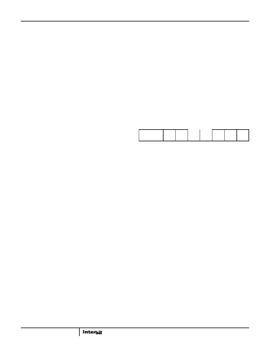
TABLE 2. ADDRESS BYTE FORMAT
0 = Write
1 = Read
A6
A5
A4
A3
A2
A1
A0
(MSB)
(LSB)
相关PDF资料 |
PDF描述 |
|---|---|
| ISL59830AIAZ-T7 | IC VIDEO DRIVER TRUE SGL 16-QSOP |
| ISL59830IA | IC DRIVER VIDEO SGL 3.3V 16-QSOP |
| ISL59832IRZ | IC VIDEO FILTER CHRG PUMP 16TQFN |
| ISL59833IAZ-T7 | IC VIDEO DRIVER TRUE SGL 16-QSOP |
| ISL59834IRZ | IC VIDEO FILTER CHRG PUMP 44-QFN |
相关代理商/技术参数 |
参数描述 |
|---|---|
| ISL59605-SPI-EVALZ | 功能描述:EVAL BOARD FOR ISL5960X RoHS:是 类别:编程器,开发系统 >> 评估演示板和套件 系列:* 标准包装:1 系列:PCI Express® (PCIe) 主要目的:接口,收发器,PCI Express 嵌入式:- 已用 IC / 零件:DS80PCI800 主要属性:- 次要属性:- 已供物品:板 |
| ISL5960X-EVALZ | 制造商:INTERSIL 制造商全称:Intersil Corporation 功能描述:MegaQ: An Automatic Composite Video Equalizer, Fully-Adaptive to 1 Mile (1600m) |
| ISL5960X-SPI-EVALZ | 制造商:INTERSIL 制造商全称:Intersil Corporation 功能描述:MegaQ: An Automatic Composite Video Equalizer, Fully-Adaptive to 1 Mile (1600m) |
| ISL5961 | 制造商:INTERSIL 制造商全称:Intersil Corporation 功能描述:14-Bit, +3.3V, 130/210+MSPS, High Speed D/A Converter |
| ISL5961/2IA | 功能描述:IC DAC 14BIT 210MSPS 28-TSSOP RoHS:否 类别:集成电路 (IC) >> 数据采集 - 数模转换器 系列:- 标准包装:2,400 系列:- 设置时间:- 位数:18 数据接口:串行 转换器数目:3 电压电源:模拟和数字 功率耗散(最大):- 工作温度:-40°C ~ 85°C 安装类型:表面贴装 封装/外壳:36-TFBGA 供应商设备封装:36-TFBGA 包装:带卷 (TR) 输出数目和类型:* 采样率(每秒):* |
发布紧急采购,3分钟左右您将得到回复。