参数资料
| 型号: | ISL6227CA-T |
| 厂商: | Intersil |
| 文件页数: | 17/27页 |
| 文件大小: | 0K |
| 描述: | IC CONTROLLER DDR, DDR2 28QSOP |
| 标准包装: | 2,500 |
| 应用: | 控制器,DDR,DDR2 |
| 输入电压: | 5 V ~ 28 V |
| 输出数: | 2 |
| 输出电压: | 0.9 V ~ 5.5 V |
| 工作温度: | -10°C ~ 100°C |
| 安装类型: | 表面贴装 |
| 封装/外壳: | 28-SSOP(0.154",3.90mm 宽) |
| 供应商设备封装: | 28-SSOP/QSOP |
| 包装: | 带卷 (TR) |
第1页第2页第3页第4页第5页第6页第7页第8页第9页第10页第11页第12页第13页第14页第15页第16页当前第17页第18页第19页第20页第21页第22页第23页第24页第25页第26页第27页
�� �
�
�ISL6227�
�output� signal� before� the� PWM� comparator� input.� This�
�effectively� creates� an� internal� current� control� loop.�
�The� resistor� connected� to� the� ISEN� pin� sets� the� gain� in� the�
�TABLE� 2.� PWM� COMPARATOR� RAMP� VOLTAGE� AMPLITUDE�
�FOR� DDR� APPLICATION�
�VRAMP�
�current� sensing.� The� following� expression� estimates� the�
�VIN� PIN� CONNECTION�
�AMPLITUDE�
�required� value� of� the� current� sense� resistor,� depending� on�
�Ch1�
�Input� Voltage�
�Input� voltage� >4.2V�
�Vin/8�
�the� maximum� continuous� load� current,� and� the� value� of� the�
�MOSFETs� r� DS(ON)� ,� assuming� the� ISEN� pin� sources� 75μA�
�current.�
�GND�
�Input� voltage� <4.2V�
�1.25V�
�1.25V�
�I� MAX� ?� r� DS� (� ON� )�
�75� μ� A�
�R� CS� =� ------------------------------------------� –� 140� Ω�
�(EQ.� 6)�
�Ch2�
�Input� voltage� >4.2V�
�GND�
�0.625V�
�1.25V�
�Because� the� current� sensing� circuit� is� a� sample-and-hold�
�type,� the� information� obtained� at� the� last� moment� of� the�
�sampling� is� used.� This� current� sensing� circuit� samples� the�
�inductor� current� very� close� to� its� peak� value.� The� current�
�The� small� signal� transfer� function� from� the� error� amplifier�
�output� voltage� V� c� to� the� output� voltage� V� o� can� be� written� in�
�Equation� 8:�
�?� ---------� +� 1� ?�
�G� (� s� )� =� G� m� ---------------------------------------� ---------------------------------------------------------�
�?� ?� -------------� +� 1� ?�
�R� i� +� DCR� +� R� o� ?� s� s�
�?� Wp1�
�?� ?� Wp2�
�?�
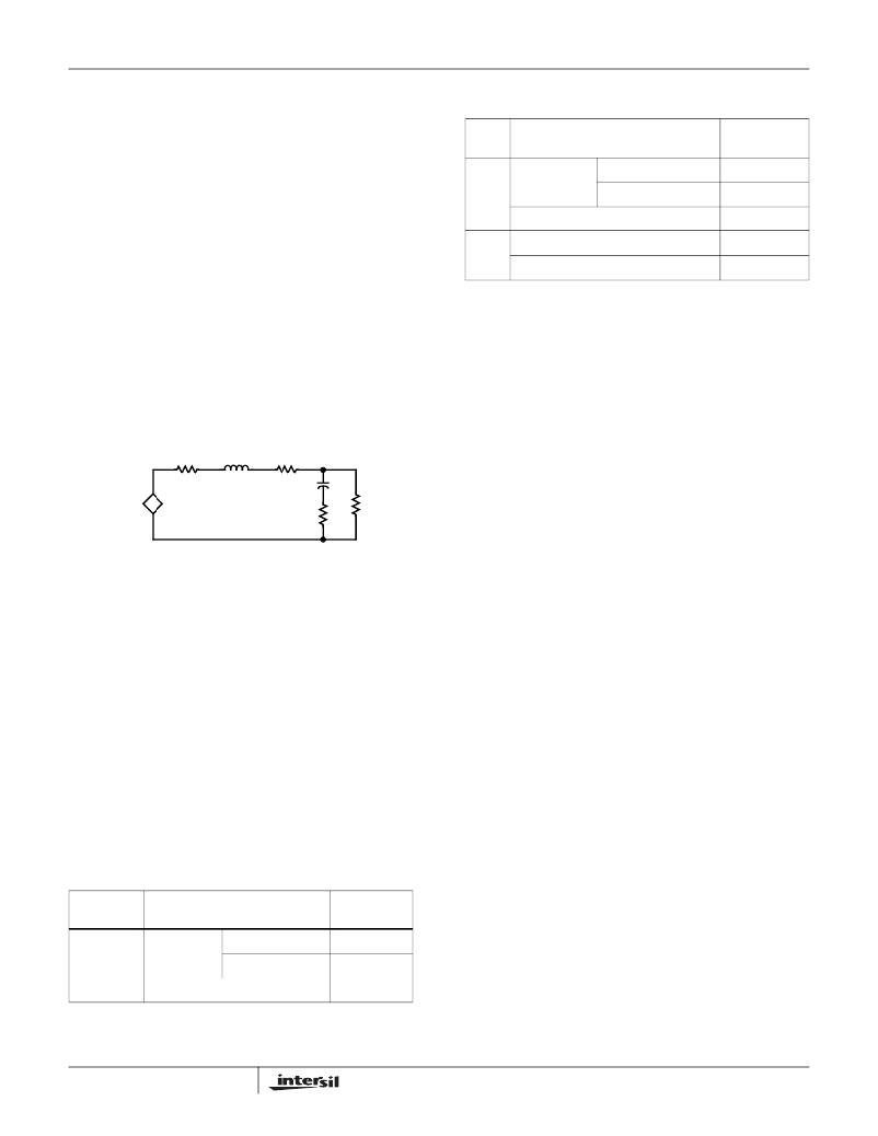
�feedback� essentially� injects� a� resistor� R� i� in� series� with� the�
�original� LC� filter� as� shown� in� Figure� 37,� where� the�
�sample-and-hold� effect� of� the� current� loop� has� been� ignored.�
�Vc� and� Vo� are� small� signal� components� extracted� from� its�
�s�
�R� o� ?� Wz� ?�
�-------------� +� 1�
�(EQ.� 8)�
�DC� operation� points.�
�The� DC� gain� is� derived� by� shorting� the� inductor� and� opening�
�Ri�
�Lo�
�DCR�
�the� capacitor.� There� is� one� zero� and� two� poles� in� this� transfer�
�Gm*Vc�
�+�
�-�
�Co�
�ESR�
�Ro�
�+�
�Vo�
�function.� The� zero� is� related� to� ESR� and� the� output�
�capacitor.�
�The� first� pole� is� a� low� frequency� pole� associated� with� the�
�-�
�FIGURE� 37.� THE� EQUIVALENT� CIRCUIT� OF� THE� POWER�
�STAGE� WITH� CURRENT� LOOP� INCLUDED�
�The� value� of� the� injected� resistor� can� be� estimated� by�
�Equation� 7:�
�output� capacitor� and� its� charging� resistors.� The� inductor� can�
�be� regarded� as� short.� The� second� pole� is� the� high� frequency�
�pole� related� to� the� inductor.� At� high� frequency� the� output�
�capacitor� can� be� regarded� as� a� short� circuit.� By�
�approximation,� the� poles� and� zero� are� inversely� proportional�
�to� the� time� constants,� associated� with� inductor� and� capacitor,�
�by� Equations� 9,� 10� and� 11:�
�R� i� =� -----------------� ----------------------------� ?� 4.4k� Ω�
�Wz� =� ------------------------�
�V� IN� r� DS� (� ON� )�
�V� ramp� R� CS� +� 140�
�(EQ.� 7)�
�1�
�ESR*C� o�
�(EQ.� 9)�
�Wp1� =� -------------------------------------------------------------------------------�
�R� i� +� DCR� +� ESR� ||� R� o�
�R� i� is� in� k� Ω,� and� r� DS� and� R� CS� are� in� Ω� .� V� IN� divided� by� V� ramp� ,�
�is� defined� as� Gm,� which� is� a� constant� 8dB� or� 18dB� for� both�
�channels� in� dual� switcher� applications,� when� V� IN� is� above�
�3V.� Refer� to� Table� 1� for� the� ramp� amplitude� in� different� V� IN�
�pin� connections.� The� feed-forward� effect� of� the� V� IN� is�
�reflected� in� Gm.� V� C� is� defined� as� the� error� amplifier� output�
�1�
�(� ESR� +� (� R� i� +� DCR� )� ||� R� o� )� *C� o�
�Wp2� =� ----------------------------------------------------------�
�L� o�
�(EQ.10)�
�(EQ.11)�
�voltage.�
�TABLE� 1.� PWM� COMPARATOR� RAMP� AMPLITUDE� FOR�
�DUAL� SWITCHER� APPLICATION�
�VRAMP�
�Since� the� current� loop� separates� the� LC� resonant� poles� into�
�two� distant� poles,� and� ESR� zero� tends� to� cancel� the� high�
�frequency� pole,� the� second� order� system� behaves� like� a� first�
�order� system.� This� control� method� simplifies� the� design� of�
�the� internal� compensator� and� makes� it� possible� to�
�VIN� PIN� CONNECTIONS�
�AMPLITUDE�
�accommodate� many� applications� having� a� wide� range� of�
�Ch1� and� Ch2� Input� Voltage�
�Input� voltage� >4.2V�
�Input� voltage� <4.2V�
�VIN/8�
�1.25V�
�parameters.�
�The� schematics� for� the� internal� compensator� is� shown� in�
�Figure� 38.�
�GND�
�17�
�1.25V�
�FN9094.7�
�May� 4,� 2009�
�相关PDF资料 |
PDF描述 |
|---|---|
| ISL6228IRTZ | IC REG CTRLR BUCK PWM 28-TQFN |
| ISL6232CAZA | IC PWR SUPPLY CONTROLLER 28QSOP |
| ISL6236AIRZ | IC MAIN PWR CTRLR QUAD 32-QFN |
| ISL6236IRZAR5281 | IC MAIN PWR CTRLR QUAD 32-QFN |
| ISL6237IRZ | IC MAIN PWR CTRLR QUAD 32-QFN |
相关代理商/技术参数 |
参数描述 |
|---|---|
| ISL6227CAZ | 功能描述:电流型 PWM 控制器 VER OF ISL6227CA RoHS:否 制造商:Texas Instruments 开关频率:27 KHz 上升时间: 下降时间: 工作电源电压:6 V to 15 V 工作电源电流:1.5 mA 输出端数量:1 最大工作温度:+ 105 C 安装风格:SMD/SMT 封装 / 箱体:TSSOP-14 |
| ISL6227CAZS2698 | 功能描述:IC CONTROLLER DDR, DDR2 28QSOP RoHS:是 类别:集成电路 (IC) >> PMIC - 稳压器 - 专用型 系列:- 标准包装:43 系列:- 应用:控制器,Intel VR11 输入电压:5 V ~ 12 V 输出数:1 输出电压:0.5 V ~ 1.6 V 工作温度:-40°C ~ 85°C 安装类型:表面贴装 封装/外壳:48-VFQFN 裸露焊盘 供应商设备封装:48-QFN(7x7) 包装:管件 |
| ISL6227CAZ-T | 功能描述:电流型 PWM 控制器 VER OF ISL6227CA-T RoHS:否 制造商:Texas Instruments 开关频率:27 KHz 上升时间: 下降时间: 工作电源电压:6 V to 15 V 工作电源电流:1.5 mA 输出端数量:1 最大工作温度:+ 105 C 安装风格:SMD/SMT 封装 / 箱体:TSSOP-14 |
| ISL6227CAZ-TS2698 | 功能描述:IC CONTROLLER DDR, DDR2 28QSOP RoHS:是 类别:集成电路 (IC) >> PMIC - 稳压器 - 专用型 系列:- 标准包装:43 系列:- 应用:控制器,Intel VR11 输入电压:5 V ~ 12 V 输出数:1 输出电压:0.5 V ~ 1.6 V 工作温度:-40°C ~ 85°C 安装类型:表面贴装 封装/外壳:48-VFQFN 裸露焊盘 供应商设备封装:48-QFN(7x7) 包装:管件 |
| ISL6227EVAL1 | 功能描述:EVALUATION BOARD 1 ISL6227 RoHS:否 类别:编程器,开发系统 >> 过时/停产零件编号 系列:- 标准包装:1 系列:- 传感器类型:CMOS 成像,彩色(RGB) 传感范围:WVGA 接口:I²C 灵敏度:60 fps 电源电压:5.7 V ~ 6.3 V 嵌入式:否 已供物品:成像器板 已用 IC / 零件:KAC-00401 相关产品:4H2099-ND - SENSOR IMAGE WVGA COLOR 48-PQFP4H2094-ND - SENSOR IMAGE WVGA MONO 48-PQFP |
发布紧急采购,3分钟左右您将得到回复。