- 您现在的位置:买卖IC网 > PDF目录383144 > ISL6292-1CR3 (INTERSIL CORP) Li-ion/Li Polymer Battery Charger PDF资料下载
参数资料
| 型号: | ISL6292-1CR3 |
| 厂商: | INTERSIL CORP |
| 元件分类: | 电源管理 |
| 英文描述: | Li-ion/Li Polymer Battery Charger |
| 中文描述: | 1-CHANNEL POWER SUPPLY SUPPORT CKT, PDSO10 |
| 封装: | 3 X 3 MM, PLASTIC, DFN-10 |
| 文件页数: | 10/19页 |
| 文件大小: | 647K |
| 代理商: | ISL6292-1CR3 |
10
FN9105.6
July 25, 2005
maximum power the IC is capable of dissipating is
dependent on the thermal impedance of the printed-circuit
board (PCB). Figure 17 shows, with dotted lines, two cases
that the charge currents are limited by the maximum power
dissipation capability due to the thermal foldback.
When using a current-limited adapter, the thermal situation
in the ISL6292 is totally different. Figure 18 shows the typical
charge curves when a current-limited adapter is employed.
The operation requires the I
REF
to be programmed higher
than the limited current I
LIM
of the adapter, as shown in
Figure 18. The key difference of the charger operating under
such conditions occurs during the CC mode.
The Block Diagram, Figure 16, aids in understanding the
operation. The current loop consists of the current amplifier
CA and the sense MOSFET Q
SEN
. The current reference I
R
is programmed by the IREF pin. The current amplifier CA
regulates the gate of the sense MOSFET Q
SEN
so that the
sensed current I
SEN
matches the reference current I
R
. The
main MOSFET Q
MAIN
and the sense MOSFET Q
SEN
form a
current mirror with a ratio of 100,000:1, that is, the output
charge current is 100,000 times I
R
. In the CC mode, the
current loop tries to increase the charge current by
enhancing the sense MOSFET Q
SEN
, so that the sensed
current matches the reference current. On the other hand,
the adapter current is limited, the actual output current will
never meet what is required by the current reference. As a
result, the current error amplifier CA keeps enhancing the
Q
SEN
as well as the main MOSFET Q
MAIN
, until they are
fully turned on. Therefore, the main MOSFET becomes a
power switch instead of a linear regulation device. The
power dissipation in the CC mode becomes:
(EQ. 2)
where r
DS(ON)
is the resistance when the main MOSFET is
fully turned on. This power is typically much less than the
peak power in the traditional linear mode.
The worst power dissipation when using a current-limited
adapter typically occurs at the beginning of the CV mode, as
shown in Figure 18. The equation EQ. 1 applies during the
CV mode. When using a very small PCB whose thermal
impedance is relatively large, it is possible that the internal
temperature can still reach the thermal foldback threshold. In
that case, the IC is thermally protected by lowering the
charge current, as shown with the dotted lines in the charge
current and power curves. Appropriate design of the adapter
can further reduce the peak power dissipation of the
ISL6292. See the Application Information section for more
information.
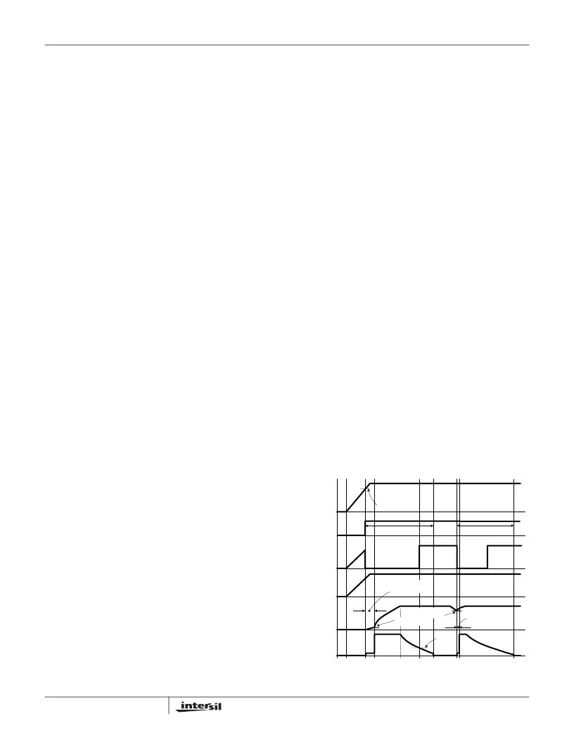
Figure 19 illustrates the typical signal waveforms for the
linear charger from the power-up to a recharge cycle. More
detailed Applications Information is given below.
Applications Information
Power on Reset (POR)
The ISL6292 resets itself as the input voltage rises above
the POR rising threshold. The V2P8 pin outputs a 2.8V
voltage, the internal oscillator starts to oscillate, the internal
timer is reset, and the charger begins to charge the battery.
The two indication pins, STATUS and FAULT, indicate a
LOW and a HIGH logic signal respectively. Figure 19
illustrates the start up of the charger between t
0
to t
2
.
The ISL6292 has a typical rising POR threshold of 3.4V and
a falling POR threshold of 2.4V. The 2.4V falling threshold
guarantees charger operation with a current-limited adapter
to minimize the thermal dissipation.
Charge Cycle
A charge cycle consists of three charge modes: trickle mode,
constant current (CC) mode, and constant voltage (CV)
mode. The charge cycle always starts with the trickle mode
until the battery voltage stays above V
MIN
(2.8V typical) for
15 consecutive cycles of the internal oscillator. If the battery
voltage drops below V
MIN
during the 15 cycles, the 15-cycle
counter is reset and the charger stays in the trickle mode.
The charger moves to the CC mode after verifying the
battery voltage. As the battery-pack terminal voltage rises to
the final charge voltage V
CH
, the CV mode begins. The
terminal voltage is regulated at the constant V
CH
in the CV
mode and the charge current is expected to decline. After
the charge current drops below I
MIN
(programmable for the
4x4 and 5X5 package and programmed to 1/10 of I
REF
for
the 3x3 package, see End-of-Charge Current for more
detail), the ISL6292 indicates the end-of-charge (EOC) with
the STATUS pin. The charging actually does not terminate
until the internal timer completes its length of TIMEOUT in
order to bring the battery to its full capacity. Signals in a
charge cycle are illustrated in Figure 19 between points t
2
to
t
5
.
P
CH
R
DS ON
)
I
CHARGE
2
=
FIGURE 19. OPERATION WAVEFORMS
VIN
V2P8
STATUS
FAULT
VBAT
I
CHARGE
15 Cycles to
1/8 TIMEOUT
15 Cycles
POR Threshold
2.8V V
MIN
V
RECHRG
t
0
t
1
t
2
t
3
t
4
t
5
t
6
t
7
t
8
Charge Cycle
Charge Cycle
I
MIN
ISL6292
相关PDF资料 |
PDF描述 |
|---|---|
| ISL6292-1CR3Z-T | Li-ion/Li Polymer Battery Charger |
| ISL6292-2CR3Z-T | Li-ion/Li Polymer Battery Charger |
| ISL6292-1CR5Z-T | Li-ion/Li Polymer Battery Charger |
| ISL6292-2CR5Z-T | Li-ion/Li Polymer Battery Charger |
| ISL6292-1CR5Z | Octal D-Type Edge-Triggered Flip-Flops with 3-State Outputs 20-TSSOP -40 to 85 |
相关代理商/技术参数 |
参数描述 |
|---|---|
| ISL6292-1CR3-T | 功能描述:IC BATT CHRGR LI-ION 4.1V 10-DFN RoHS:否 类别:集成电路 (IC) >> PMIC - 电池管理 系列:- 标准包装:1 系列:- 功能:充电管理 电池化学:锂离子(Li-Ion)、锂聚合物(Li-Pol) 电源电压:3.75 V ~ 6 V 工作温度:-40°C ~ 85°C 安装类型:表面贴装 封装/外壳:SC-74A,SOT-753 供应商设备封装:SOT-23-5 包装:剪切带 (CT) 产品目录页面:669 (CN2011-ZH PDF) 其它名称:MCP73831T-2ACI/OTCT |
| ISL6292-1CR3Z | 功能描述:电池管理 LD VER OF ISL6292-1C R3 RoHS:否 制造商:Texas Instruments 电池类型:Li-Ion 输出电压:5 V 输出电流:4.5 A 工作电源电压:3.9 V to 17 V 最大工作温度:+ 85 C 最小工作温度:- 40 C 封装 / 箱体:VQFN-24 封装:Reel |
| ISL6292-1CR3Z-T | 功能描述:电池管理 LD VER OF ISL6292-1C R3-T RoHS:否 制造商:Texas Instruments 电池类型:Li-Ion 输出电压:5 V 输出电流:4.5 A 工作电源电压:3.9 V to 17 V 最大工作温度:+ 85 C 最小工作温度:- 40 C 封装 / 箱体:VQFN-24 封装:Reel |
| ISL6292-1CR4 | 功能描述:IC BATT CHRGR LI-ION 4.1V 16-QFN RoHS:否 类别:集成电路 (IC) >> PMIC - 电池管理 系列:- 标准包装:1 系列:- 功能:充电管理 电池化学:锂离子(Li-Ion)、锂聚合物(Li-Pol) 电源电压:3.75 V ~ 6 V 工作温度:-40°C ~ 85°C 安装类型:表面贴装 封装/外壳:SC-74A,SOT-753 供应商设备封装:SOT-23-5 包装:剪切带 (CT) 产品目录页面:669 (CN2011-ZH PDF) 其它名称:MCP73831T-2ACI/OTCT |
| ISL6292-1CR4-T | 功能描述:IC BATT CHRGR LI-ION 4.1V 16-QFN RoHS:否 类别:集成电路 (IC) >> PMIC - 电池管理 系列:- 标准包装:1 系列:- 功能:充电管理 电池化学:锂离子(Li-Ion)、锂聚合物(Li-Pol) 电源电压:3.75 V ~ 6 V 工作温度:-40°C ~ 85°C 安装类型:表面贴装 封装/外壳:SC-74A,SOT-753 供应商设备封装:SOT-23-5 包装:剪切带 (CT) 产品目录页面:669 (CN2011-ZH PDF) 其它名称:MCP73831T-2ACI/OTCT |
发布紧急采购,3分钟左右您将得到回复。