- 您现在的位置:买卖IC网 > PDF目录16622 > ISL6443IRZ-TK (Intersil)IC CTRLR PWM DUAL 300KHZ 28-QFN PDF资料下载
参数资料
| 型号: | ISL6443IRZ-TK |
| 厂商: | Intersil |
| 文件页数: | 11/18页 |
| 文件大小: | 0K |
| 描述: | IC CTRLR PWM DUAL 300KHZ 28-QFN |
| 产品培训模块: | Solutions for Industrial Control Applications |
| 标准包装: | 1,000 |
| 应用: | 电源 |
| 电流 - 电源: | 50µA |
| 电源电压: | 5.6 V ~ 24 V |
| 工作温度: | -40°C ~ 85°C |
| 安装类型: | 表面贴装 |
| 封装/外壳: | 28-VFQFN 裸露焊盘 |
| 供应商设备封装: | 28-QFN 裸露焊盘(5x5) |
| 包装: | 带卷 (TR) |
�� �
�
�ISL6443�
�T� SOFT� =� 0.8V� ?� -----------� ?�
�V� OUTx� =� 0.8V� ?� ----------------------� ?�
�Functional� Description�
�General� Description�
�The� ISL6443� integrates� control� circuits� for� two� synchronous�
�buck� converters� and� one� linear� controller.� The� two�
�synchronous� bucks� operate� out� of� phase� to� substantially�
�reduce� the� input� ripple� and� thus� reduce� the� input� filter�
�requirements.� The� chip� has� four� control� lines� (SS1,� SD1,�
�SS2,� and� SD2),� which� provide� independent� control� for� each�
�of� the� synchronous� buck� outputs.�
�The� buck� PWM� controllers� employ� a� free-running� frequency�
�of� 300kHz.� The� current� mode� control� scheme� with� an� input�
�voltage� feed-forward� ramp� input� to� the� modulator� provides�
�excellent� rejection� of� input� voltage� variations� and� provides�
�simplified� loop� compensations.�
�The� linear� controller� can� drive� either� a� PNP� or� PFET� to� provide�
�ultra� low-dropout� regulation� with� programmable� voltages.�
�Internal� 5V� Linear� Regulator� (VCC_5V)�
�All� ISL6443� functions� are� internally� powered� from� an� on-�
�chip,� low� dropout� 5V� regulator.� The� maximum� regulator� input�
�voltage� is� 24V.� Bypass� the� regulator� ’s� output� (VCC_5V)� with�
�a� 4.7μF� capacitor� to� ground.� The� dropout� voltage� for� this�
�LDO� is� typically� 600mV,� so� when� VCC_5V� is� greater� than�
�5.6V,� VCC_5V� is� typically� 5V.� The� ISL6443� also� employs� an�
�undervoltage� lockout� circuit� that� disables� both� regulators�
�when� VCC_5V� falls� below� 4.4V.�
�The� internal� LDO� can� source� over� 60mA� to� supply� the� IC,�
�power� the� low� side� gate� drivers,� charge� the� external� boot�
�capacitor� and� supply� small� external� loads.� When� driving�
�large� FETs� especially� at� 300kHz� frequency,� little� or� no�
�regulator� current� may� be� available� for� external� loads.�
�For� example,� a� single� large� FET� with� 15nC� total� gate� charge�
�requires� 15nC� x� 300kHz� =� 4.5mA.� Also,� at� higher� input�
�voltages� with� larger� FETs,� the� power� dissipation� across� the�
�internal� 5V� will� increase.� Excessive� dissipation� across� this�
�regulator� must� be� avoided� to� prevent� junction� temperature�
�rise.� Larger� FETs� can� be� used� with� 5V� ±10%� input�
�applications.� The� thermal� overload� protection� circuit� will� be�
�triggered,� if� the� VCC_5V� output� is� short� circuited.� Connect�
�VCC_5V� to� V� IN� for� 5V� ±10%� input� applications.�
�Soft-Start� Operation�
�When� soft-start� is� initiated,� the� voltage� on� the� SS� pin� of� the�
�enabled� PWM� channels� starts� to� ramp� gradually,� due� to� the�
�5� μ� A� current� sourced� into� the� external� capacitor.� The� output�
�voltage� follows� the� soft-start� voltage.�
�When� the� SS� pin� voltage� reaches� 0.8V,� the� output� voltage� of�
�the� enabled� PWM� channel� reaches� the� regulation� point,� and�
�the� soft-start� pin� voltage� continues� to� rise.� At� this� point� the�
�PGOOD� and� fault� circuitry� is� enabled.� This� completes� the�
�soft-start� sequence.� Any� further� rise� of� SS� pin� voltage� does�
�not� affect� the� output� voltage.� By� varying� the� values� of� the�
�soft-start� capacitors,� it� is� possible� to� provide� sequencing� of� the�
�11�
�main� outputs� at� start-up.� The� soft-start� time� can� be� obtained�
�from� the� following� equation:�
�C� SS�
�?� 5� μ� A� ?�
�VCC_5V 1V/DIV�
�V� OUT1� 1V/DIV�
�SS1 1V/DIV�
�FIGURE� 13.� SOFT-START� OPERATION�
�The� soft-start� capacitors� can� be� chosen� to� provide� startup�
�tracking� for� the� two� PWM� outputs.� This� can� be� achieved� by�
�choosing� the� soft-start� capacitors� such� that� the� soft-start�
�capacitor� ration� equals� the� respective� PWM� output� voltage�
�ratio.� For� example,� if� I� use� PWM1� =� 1.2V� and� PWM2� =� 3.3V�
�then� the� soft-start� capacitor� ratio� should� be,� C� SS1� /C� SS1� =�
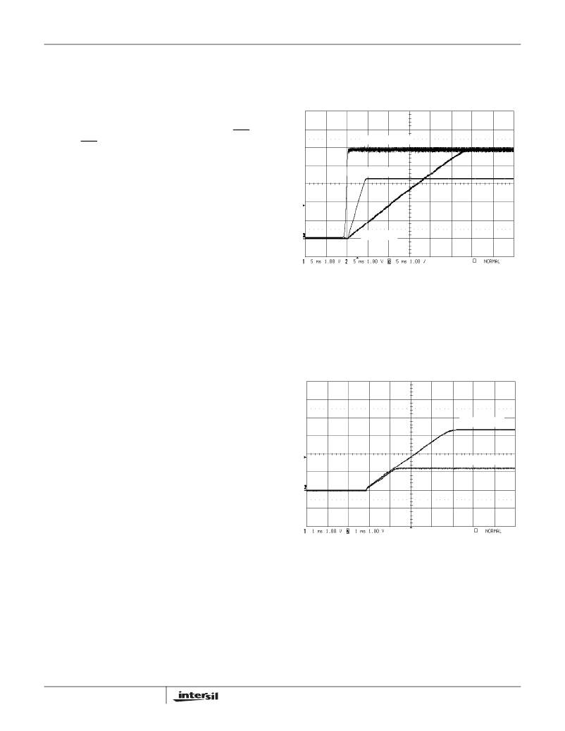
�1.2/3.3� =� 0.364.� Figure� 14� shows� that� soft-start� waveform�
�with� C� SS1� =� 0.01μF� and� C� SS2� =� 0.027μF.�
�V� OUT1� 1V/DIV�
�V� OUT2� 1V/DIV�
�FIGURE� 14.� PWM1� AND� PWM2� OUTPUT� TRACKING� DURING�
�STARTUP�
�Output� Voltage� Programming�
�A� resistive� divider� from� the� output� to� ground� sets� the� output�
�voltage� of� either� PWM� channel.� The� center� point� of� the�
�divider� shall� be� connected� to� FBx� pin.� The� output� voltage�
�value� is� determined� by� the� following� equation.�
�R1� +� R2�
�?� R2� ?�
�where� R1� is� the� top� resistor� of� the� feedback� divider� network�
�and� R2� is� the� resistor� connected� from� FBx� to� ground.�
�FN9044.2�
�August� 9,� 2006�
�相关PDF资料 |
PDF描述 |
|---|---|
| ISL6443IRZ-T | IC CTRLR PWM DUAL 300KHZ 28-QFN |
| H3CKH-1418G | IDC CABLE - HKC14H/AE14G/HPK14H |
| PX0851/4M00 | CABLE IP68 6POS-4POS FIREWIRE 4M |
| A3982SLBTR-T | IC MOTOR DRIVER STEPPER 24-SOIC |
| Q2-Z-1 1/2-01-MS50FT | HEATSHRK POLY Q2Z 1-1/2"X50' BLK |
相关代理商/技术参数 |
参数描述 |
|---|---|
| ISL6443IRZ-TKS2698 | 制造商:Intersil Corporation 功能描述:LEAD-FREE DUAL PWM CONTROLLER + LINEAR CONT., 300KHZ, QFN, 5 - Tape and Reel 制造商:Rochester Electronics LLC 功能描述: |
| ISL6443IRZ-TS2698 | 制造商:Intersil Corporation 功能描述:LEAD-FREE DUAL PWM CONTROLLER + LINEAR CONTROLLER, 300KHZ, Q - Tape and Reel |
| ISL6444CA | 功能描述:电流型 PWM 控制器 Dual with DDR Memory RoHS:否 制造商:Texas Instruments 开关频率:27 KHz 上升时间: 下降时间: 工作电源电压:6 V to 15 V 工作电源电流:1.5 mA 输出端数量:1 最大工作温度:+ 105 C 安装风格:SMD/SMT 封装 / 箱体:TSSOP-14 |
| ISL6444CA-T | 功能描述:IC CONTROLLER DDR 28-QSOP RoHS:否 类别:集成电路 (IC) >> PMIC - 稳压器 - 专用型 系列:- 产品培训模块:Lead (SnPb) Finish for COTS Obsolescence Mitigation Program 标准包装:2,000 系列:- 应用:电源,ICERA E400,E450 输入电压:4.1 V ~ 5.5 V 输出数:10 输出电压:可编程 工作温度:-40°C ~ 85°C 安装类型:表面贴装 封装/外壳:42-WFBGA,WLCSP 供应商设备封装:42-WLP 包装:带卷 (TR) |
| ISL6444CAZ | 功能描述:IC CONTROLLER DDR 28-QSOP RoHS:是 类别:集成电路 (IC) >> PMIC - 稳压器 - 专用型 系列:- 标准包装:43 系列:- 应用:控制器,Intel VR11 输入电压:5 V ~ 12 V 输出数:1 输出电压:0.5 V ~ 1.6 V 工作温度:-40°C ~ 85°C 安装类型:表面贴装 封装/外壳:48-VFQFN 裸露焊盘 供应商设备封装:48-QFN(7x7) 包装:管件 |
发布紧急采购,3分钟左右您将得到回复。