- 您现在的位置:买卖IC网 > PDF目录15526 > ISL6520BCBZ (Intersil)IC REG CTRLR BUCK PWM VM 8-SOIC PDF资料下载
参数资料
| 型号: | ISL6520BCBZ |
| 厂商: | Intersil |
| 文件页数: | 5/10页 |
| 文件大小: | 0K |
| 描述: | IC REG CTRLR BUCK PWM VM 8-SOIC |
| 标准包装: | 98 |
| PWM 型: | 电压模式 |
| 输出数: | 1 |
| 频率 - 最大: | 340kHz |
| 占空比: | 100% |
| 电源电压: | 4.5 V ~ 5.5 V |
| 降压: | 是 |
| 升压: | 无 |
| 回扫: | 无 |
| 反相: | 无 |
| 倍增器: | 无 |
| 除法器: | 无 |
| Cuk: | 无 |
| 隔离: | 无 |
| 工作温度: | 0°C ~ 70°C |
| 封装/外壳: | 8-SOIC(0.154",3.90mm 宽) |
| 包装: | 管件 |
| 产品目录页面: | 1243 (CN2011-ZH PDF) |
�� �
�
�ISL6520B�
�rail,� which� supplies� the� bias� voltage� to� the� ISL6520B.� If� there�
�is� nowhere� for� this� current� to� go,� such� as� to� other� distributed�
�loads� on� the� V� CC� rail,� through� a� voltage� limiting� protection�
�as� close� as� practical� to� the� BOOT� and� PHASE� pins.� All�
�components� used� for� feedback� compensation� should� be�
�located� as� close� to� the� IC� a� practical.�
�device,� or� other� methods,� the� capacitance� on� the� V� CC� bus�
�will� absorb� the� current.� This� situation� will� allow� voltage� level�
�of� the� V� CC� rail� to� increase.� If� the� voltage� level� of� the� rail� is�
�boosted� to� a� level� that� exceeds� the� maximum� voltage� rating�
�of� the� ISL6520B,� then� the� IC� will� experience� an� irreversible�
�failure� and� the� converter� will� no� longer� be� operational.�
�ISL6520B�
�BOOT�
�C� BOOT�
�PHASE�
�VCC�
�+5V�
�D� 1�
�+V� IN�
�Q� 1�
�Q� 2�
�L� O�
�C� O�
�V� OUT�
�Ensuring� that� there� is� a� path� for� the� current� to� follow� other�
�than� the� capacitance� on� the� rail� will� prevent� this� failure�
�mode.�
�Application� Guidelines�
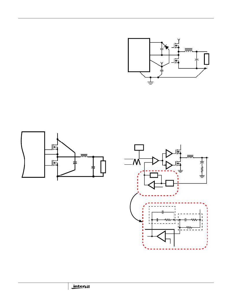
�Layout� Considerations�
�As� in� any� high� frequency� switching� converter,� layout� is� very�
�important.� Switching� current� from� one� power� device� to� another�
�can� generate� voltage� transients� across� the� impedances� of� the�
�interconnecting� bond� wires� and� circuit� traces.� These�
�interconnecting� impedances� should� be� minimized� by� using�
�wide,� short� printed� circuit� traces.� The� critical� components�
�should� be� located� as� close� together� as� possible,� using� ground�
�plane� construction� or� single� point� grounding.�
�V� IN�
�ISL6520B�
�C� VCC�
�GND�
�FIGURE� 3.� PRINTED� CIRCUIT� BOARD� SMALL� SIGNAL�
�LAYOUT� GUIDELINES�
�Feedback� Compensation�
�Figure� 4� highlights� the� voltage-mode� control� loop� for� a�
�synchronous-rectified� buck� converter.� The� output� voltage�
�(V� OUT� )� is� regulated� to� the� Reference� voltage� level.� The�
�error� amplifier� (Error� Amp)� output� (V� E/A� )� is� compared� with�
�the� oscillator� (OSC)� triangular� wave� to� provide� a�
�pulse-width� modulated� (PWM)� wave� with� an� amplitude� of�
�V� IN� at� the� PHASE� node.� The� PWM� wave� is� smoothed� by� the�
�output� filter� (L� O� and� C� O� ).�
�UGATE�
�PHASE�
�Q� 1�
�L� O�
�V� OUT�
�OSC�
�PWM�
�COMPARATOR�
�DRIVER�
�V� IN�
�L� O�
�V� OUT�
�LGATE�
�Q� 2�
�C� IN�
�C� O�
�Δ� V� OSC�
�-�
�+�
�DRIVER�
�PHASE�
�C� O�
�ESR�
�Z� FB�
�(PARASITIC)�
�RETURN�
�FIGURE� 2.� PRINTED� CIRCUIT� BOARD� POWER� AND�
�V� E/A�
�-�
�+�
�Z� IN�
�GROUND� PLANES� OR� ISLANDS�
�ERROR�
�REFERENCE�
�AMP�
�Figure� 2� shows� the� critical� power� components� of� the� converter.�
�To� minimize� the� voltage� overshoot,� the� interconnecting� wires�
�DETAILED� COMPENSATION� COMPONENTS�
�indicated� by� heavy� lines� should� be� part� of� a� ground� or� power�
�plane� in� a� printed� circuit� board.� The� components� shown� in�
�Figure� 2� should� be� located� as� close� together� as� possible.�
�Please� note� that� the� capacitors� C� IN� and� C� O� may� each�
�C� 1�
�C� 2�
�R� 2�
�Z� FB�
�C� 3�
�Z� IN�
�R� 3�
�V� OUT�
�represent� numerous� physical� capacitors.� Locate� the� ISL6520B�
�within� 3� inches� of� the� MOSFETs,� Q� 1� and� Q� 2� .� The� circuit� traces�
�for� the� MOSFETs’� gate� and� source� connections� from� the�
�COMP/SD�
�-�
�FB�
�R� 1�
�ISL6520B� must� be� sized� to� handle� up� to� 1A� peak� current.�
�Figure� 3� shows� the� circuit� traces� that� require� additional�
�layout� consideration.� Use� single� point� and� ground� plane�
�construction� for� the� circuits� shown.� Minimize� any� leakage�
�current� paths� on� the� COMP/SD� pin� and� locate� the� resistor,�
�R� OSCET� close� to� the� COMP/SD� pin� because� the� internal�
�current� source� is� only� 20� μ� A.� Provide� local� V� CC� decoupling�
�between� VCC� and� GND� pins.� Locate� the� capacitor,� C� BOOT�
�5�
�+�
�ISL6520B�
�REFERENCE�
�FIGURE� 4.� VOLTAGE-MODE� BUCK� CONVERTER�
�COMPENSATION� DESIGN�
�FN9083.3�
�July� 23,� 2007�
�相关PDF资料 |
PDF描述 |
|---|---|
| ISL6526ACBZ | IC REG CTRLR BUCK PWM VM 14-SOIC |
| V300C48C75B3 | CONVERTER MOD DC/DC 48V 75W |
| UVZ1E222MHD | CAP ALUM 2200UF 25V 20% RADIAL |
| V300C48C75B2 | CONVERTER MOD DC/DC 48V 75W |
| ADZS-BF548-EZLITE | KIT EZLITE ADZS-BF548 |
相关代理商/技术参数 |
参数描述 |
|---|---|
| ISL6520BCBZ-T | 功能描述:IC REG CTRLR BUCK PWM VM 8-SOIC RoHS:是 类别:集成电路 (IC) >> PMIC - 稳压器 - DC DC 切换控制器 系列:- 产品培训模块:Lead (SnPb) Finish for COTS Obsolescence Mitigation Program 标准包装:2,500 系列:- PWM 型:电流模式 输出数:1 频率 - 最大:275kHz 占空比:50% 电源电压:18 V ~ 110 V 降压:无 升压:无 回扫:无 反相:无 倍增器:无 除法器:无 Cuk:无 隔离:是 工作温度:-40°C ~ 85°C 封装/外壳:8-SOIC(0.154",3.90mm 宽) 包装:带卷 (TR) |
| ISL6520BCR | 功能描述:IC REG CTRLR BUCK PWM VM 16-QFN RoHS:否 类别:集成电路 (IC) >> PMIC - 稳压器 - DC DC 切换控制器 系列:- 标准包装:4,000 系列:- PWM 型:电压模式 输出数:1 频率 - 最大:1.5MHz 占空比:66.7% 电源电压:4.75 V ~ 5.25 V 降压:是 升压:无 回扫:无 反相:无 倍增器:无 除法器:无 Cuk:无 隔离:无 工作温度:-40°C ~ 85°C 封装/外壳:40-VFQFN 裸露焊盘 包装:带卷 (TR) |
| ISL6520BCR-T | 功能描述:IC REG CTRLR BUCK PWM VM 16-QFN RoHS:否 类别:集成电路 (IC) >> PMIC - 稳压器 - DC DC 切换控制器 系列:- 标准包装:4,000 系列:- PWM 型:电压模式 输出数:1 频率 - 最大:1.5MHz 占空比:66.7% 电源电压:4.75 V ~ 5.25 V 降压:是 升压:无 回扫:无 反相:无 倍增器:无 除法器:无 Cuk:无 隔离:无 工作温度:-40°C ~ 85°C 封装/外壳:40-VFQFN 裸露焊盘 包装:带卷 (TR) |
| ISL6520BIR | 功能描述:IC REG CTRLR BUCK PWM VM 16-QFN RoHS:否 类别:集成电路 (IC) >> PMIC - 稳压器 - DC DC 切换控制器 系列:- 标准包装:4,000 系列:- PWM 型:电压模式 输出数:1 频率 - 最大:1.5MHz 占空比:66.7% 电源电压:4.75 V ~ 5.25 V 降压:是 升压:无 回扫:无 反相:无 倍增器:无 除法器:无 Cuk:无 隔离:无 工作温度:-40°C ~ 85°C 封装/外壳:40-VFQFN 裸露焊盘 包装:带卷 (TR) |
| ISL6520BIR-T | 功能描述:IC REG CTRLR BUCK PWM VM 16-QFN RoHS:否 类别:集成电路 (IC) >> PMIC - 稳压器 - DC DC 切换控制器 系列:- 标准包装:4,000 系列:- PWM 型:电压模式 输出数:1 频率 - 最大:1.5MHz 占空比:66.7% 电源电压:4.75 V ~ 5.25 V 降压:是 升压:无 回扫:无 反相:无 倍增器:无 除法器:无 Cuk:无 隔离:无 工作温度:-40°C ~ 85°C 封装/外壳:40-VFQFN 裸露焊盘 包装:带卷 (TR) |
发布紧急采购,3分钟左右您将得到回复。