参数资料
| 型号: | ISL6554CBZA |
| 厂商: | Intersil |
| 文件页数: | 13/16页 |
| 文件大小: | 0K |
| 描述: | IC PWM CORE VOLTAGE REG 20-SOIC |
| 标准包装: | 380 |
| 应用: | 控制器,Intel Itanium? |
| 输入电压: | 4.75 V ~ 5.25 V |
| 输出数: | 4 |
| 输出电压: | 0.95 V ~ 1.7 V |
| 工作温度: | 0°C ~ 70°C |
| 安装类型: | 表面贴装 |
| 封装/外壳: | 20-SOIC(0.295",7.50mm 宽) |
| 供应商设备封装: | 20-SOIC W |
| 包装: | 管件 |
�� �
�
�ISL6554�
�V� IN� –� V� OUT� V� OUT�
�F� SW� � L�
�copper� filled� polygons� on� the� top� and� bottom� circuit� layers� for�
�the� phase� nodes.� Use� the� remaining� printed� circuit� layers� for�
�small� signal� wiring.� The� wiring� traces� from� the� driver� IC� to� the�
�MOSFET� gate� and� source� should� be� sized� to� carry� at� least�
�one� ampere� of� current.�
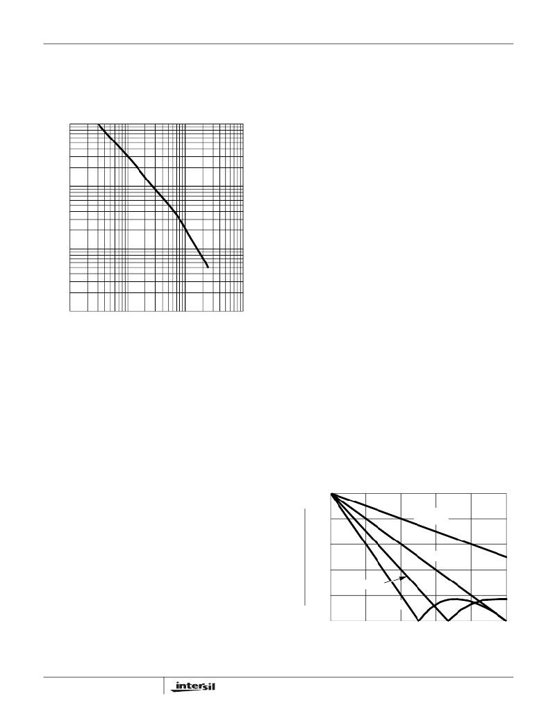
�1,000�
�500�
�200�
�100�
�50�
�20�
�10�
�5�
�2�
�1�
�10� 20� 50� 100� 200� 500� 1,000� 2,000� 5,000� 10,000�
�CHANNEL� OSCILLATOR� FREQUENCY,� F� SW� (kHz)�
�FIGURE� 10.� RESISTANCE� R� T� vs� FREQUENCY�
�Component� Selection� Guidelines�
�Output� Capacitor� Selection�
�The� output� capacitor� is� selected� to� meet� both� the� dynamic�
�load� requirements� and� the� voltage� ripple� requirements.� The�
�load� transient� for� the� microprocessor� CORE� is� characterized�
�by� high� slew� rate� (di/dt)� current� demands.� In� general,�
�multiple� high� quality� capacitors� of� different� size� and� dielectric�
�are� paralleled� to� meet� the� design� constraints.�
�Modern� microprocessors� produce� severe� transient� load� rates.�
�High� frequency� capacitors� supply� the� initially� transient� current�
�and� slow� the� load� rate-of-change� seen� by� the� bulk� capacitors.�
�The� bulk� filter� capacitor� values� are� generally� determined� by�
�Bulk� capacitor� choices� include� aluminum� electrolytic,� OS-�
�Con,� Tantalum� and� even� ceramic� dielectrics.� An� aluminum�
�electrolytic� capacitor� ’s� ESR� value� is� related� to� the� case� size�
�with� lower� ESR� available� in� larger� case� sizes.� However,� the�
�equivalent� series� inductance� (ESL)� of� these� capacitors�
�increases� with� case� size� and� can� reduce� the� usefulness� of�
�the� capacitor� to� high� slew-rate� transient� loading.�
�Unfortunately,� ESL� is� not� a� specified� parameter.� Consult� the�
�capacitor� manufacturer� and� measure� the� capacitor� ’s�
�impedance� with� frequency� to� select� a� suitable� component.�
�Output� Inductor� Selection�
�One� of� the� parameters� limiting� the� converter� ’s� response� to� a�
�load� transient� is� the� time� required� to� change� the� inductor�
�current.� Small� inductors� in� a� multi-phase� converter� reduces�
�the� response� time� without� significant� increases� in� total� ripple�
�current.�
�The� output� inductor� of� each� power� channel� controls� the�
�ripple� current.� The� control� IC� is� stable� for� channel� ripple�
�current� (peak-to-peak)� up� to� twice� the� average� current.� A�
�single� channel’s� ripple� current� is� approximately:�
�?� I� =� --------------------------------� � ----------------�
�V� IN�
�The� current� from� multiple� channels� tend� to� cancel� each� other�
�and� reduce� the� total� ripple� current.� Figure� 12� gives� the� total�
�ripple� current� as� a� function� of� duty� cycle,� normalized� to� the�
�parameter� (� Vo� )� ?� (� LxF� SW� )� at� zero� duty� cycle.� To� determine�
�the� total� ripple� current� from� the� number� of� channels� and� the�
�duty� cycle,� multiply� the� y-axis� value� by� (� Vo� )� ?� (� LxF� SW� )� .�
�Small� values� of� output� inductance� can� cause� excessive�
�power� dissipation.� The� ISL6554� is� designed� for� stable�
�operation� for� ripple� currents� up� to� twice� the� load� current.�
�However,� for� this� condition,� the� RMS� current� is� 115%� above�
�the� value� shown� in� the� following� MOSFET� Selection� and�
�Considerations� section.� With� all� else� fixed,� decreasing� the�
�inductance� could� increase� the� power� dissipated� in� the�
�MOSFETs� by� 30%.�
�1.0�
�the� ESR� (effective� series� resistance)� and� voltage� rating�
�requirements� rather� than� actual� capacitance� requirements.�
�High� frequency� decoupling� capacitors� should� be� placed� as�
�0.8�
�SINGLE�
�CHANNEL�
�close� to� the� power� pins� of� the� load� as� physically� possible.� Be�
�careful� not� to� add� inductance� in� the� circuit� board� wiring� that�
�could� cancel� the� usefulness� of� these� low� inductance�
�0.6�
�0.4�
�2 CHANNEL�
�components.� Consult� with� the� manufacturer� of� the� load� on�
�specific� decoupling� requirements.�
�Use� only� specialized� low-ESR� capacitors� intended� for�
�0.2�
�3 CHANNEL�
�4 CHANNEL�
�switching-regulator� applications� for� the� bulk� capacitors.� The�
�bulk� capacitor� ’s� ESR� determines� the� output� ripple� voltage�
�0�
�0�
�0.1�
�0.2�
�0.3�
�0.4�
�0.5�
�and� the� initial� voltage� drop� following� a� high� slew-rate�
�transient’s� edge.� In� most� cases,� multiple� capacitors� of� small�
�case� size� perform� better� than� a� single� large� case� capacitor.�
�13�
�DUTY� CYCLE� (V� O� /V� IN� )�
�FIGURE� 11.� RIPPLE� CURRENT� vs� DUTY� CYCLE�
�FN9003.3�
�February� 11,� 2005�
�相关PDF资料 |
PDF描述 |
|---|---|
| GBB91DHRT-S578 | CONN EDGECARD 182POS .050 EXTEND |
| X40235S16I-A | IC VOLTAGE MON TRPL EE 16-SOIC |
| 450MXG390MEFCSN30X45 | CAP ALUM 390UF 450V 20% SNAP-IN |
| 0925-392K | COIL RF 3.9UH MOLDED SHIELDED |
| AYM12DTMD-S664 | CONN EDGECARD 24POS R/A .156 |
相关代理商/技术参数 |
参数描述 |
|---|---|
| ISL6554CBZA-T | 功能描述:IC PWM CORE VOLTAGE REG 20-SOIC RoHS:是 类别:集成电路 (IC) >> PMIC - 稳压器 - 专用型 系列:- 产品培训模块:Lead (SnPb) Finish for COTS Obsolescence Mitigation Program 标准包装:2,000 系列:- 应用:电源,ICERA E400,E450 输入电压:4.1 V ~ 5.5 V 输出数:10 输出电压:可编程 工作温度:-40°C ~ 85°C 安装类型:表面贴装 封装/外壳:42-WFBGA,WLCSP 供应商设备封装:42-WLP 包装:带卷 (TR) |
| ISL6554CBZ-T | 功能描述:IC PWM CORE VOLTAGE REG 20-SOIC RoHS:是 类别:集成电路 (IC) >> PMIC - 稳压器 - 专用型 系列:- 产品培训模块:Lead (SnPb) Finish for COTS Obsolescence Mitigation Program 标准包装:2,000 系列:- 应用:电源,ICERA E400,E450 输入电压:4.1 V ~ 5.5 V 输出数:10 输出电压:可编程 工作温度:-40°C ~ 85°C 安装类型:表面贴装 封装/外壳:42-WFBGA,WLCSP 供应商设备封装:42-WLP 包装:带卷 (TR) |
| ISL6554CBZ-TR5165 | 功能描述:IC PWM CORE VOLTAGE REG 20-SOIC RoHS:是 类别:集成电路 (IC) >> PMIC - 稳压器 - 专用型 系列:- 产品培训模块:Lead (SnPb) Finish for COTS Obsolescence Mitigation Program 标准包装:2,000 系列:- 应用:电源,ICERA E400,E450 输入电压:4.1 V ~ 5.5 V 输出数:10 输出电压:可编程 工作温度:-40°C ~ 85°C 安装类型:表面贴装 封装/外壳:42-WFBGA,WLCSP 供应商设备封装:42-WLP 包装:带卷 (TR) |
| ISL6556ACB | 功能描述:IC CTRLR MULTIPHASE VRM10 28SOIC RoHS:否 类别:集成电路 (IC) >> PMIC - 稳压器 - 专用型 系列:- 产品培训模块:Lead (SnPb) Finish for COTS Obsolescence Mitigation Program 标准包装:2,000 系列:- 应用:电源,ICERA E400,E450 输入电压:4.1 V ~ 5.5 V 输出数:10 输出电压:可编程 工作温度:-40°C ~ 85°C 安装类型:表面贴装 封装/外壳:42-WFBGA,WLCSP 供应商设备封装:42-WLP 包装:带卷 (TR) |
| ISL6556ACBR5208 | 制造商:Rochester Electronics LLC 功能描述: 制造商:Intersil Corporation 功能描述: |
发布紧急采购,3分钟左右您将得到回复。