- 您现在的位置:买卖IC网 > PDF目录15178 > ISL6559CRZ-T (Intersil)IC REG CTRLR BUCK PWM VM 32-QFN PDF资料下载
参数资料
| 型号: | ISL6559CRZ-T |
| 厂商: | Intersil |
| 文件页数: | 16/21页 |
| 文件大小: | 0K |
| 描述: | IC REG CTRLR BUCK PWM VM 32-QFN |
| 标准包装: | 6,000 |
| PWM 型: | 电压模式 |
| 输出数: | 1 |
| 频率 - 最大: | 4MHz |
| 占空比: | 75% |
| 电源电压: | 4.75 V ~ 5.25 V |
| 降压: | 是 |
| 升压: | 无 |
| 回扫: | 无 |
| 反相: | 无 |
| 倍增器: | 无 |
| 除法器: | 无 |
| Cuk: | 无 |
| 隔离: | 无 |
| 工作温度: | 0°C ~ 70°C |
| 封装/外壳: | 32-VFQFN 裸露焊盘 |
| 包装: | 带卷 (TR) |
�� �
�
�ISL6559�
�each� of� the� three� cases� which� follow,� there� is� a� separate� set�
�of� equations� for� the� compensation� components.�
�C� 2�
�-------------------� >� f� 0�
�R� C� =� R� FB� ------------------------------------�
�0.75V�
�2� π� V� PP� R� FB� f� 0�
�-------------------� ≤� f� 0� <� ------------------------------�
�Case� 1:�
�Case� 2:�
�1�
�2� π� LC�
�2� π� f� 0� V� pp� LC�
�IN�
�0.75V� IN�
�C� C� =� ------------------------------------�
�1� 1�
�2� π� LC� 2� π� C� (� ESR� )�
�C� 1�
�R� 1�
�R� C�
�R� FB�
�C� C�
�COMP�
�FB�
�IOUT�
�VDIFF�
�R� C� =� R� FB� --------------------------------------------�
�(� 2� π� )� 2� f� 02� V� PP� R� FB� LC�
�V� PP� (� 2� π� )� 2� f� 02� LC�
�0.75� V� IN�
�0.75V� IN�
�C� C� =� -------------------------------------------------------------�
�(EQ.� 23)�
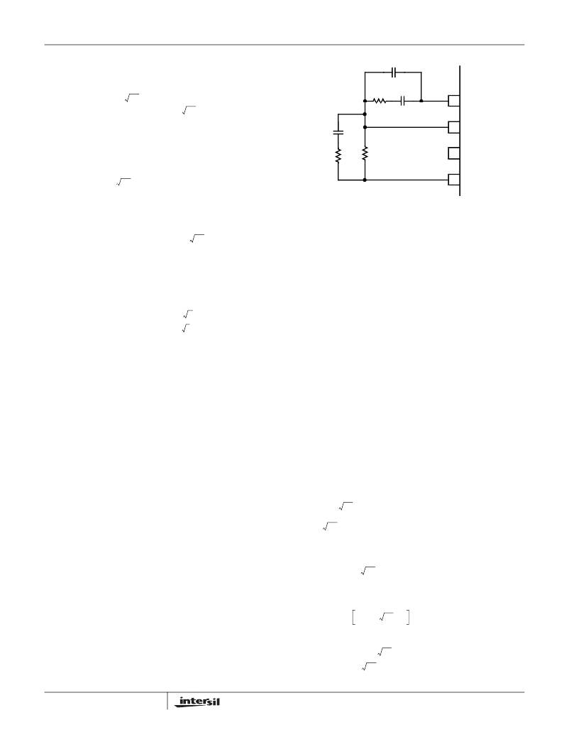
�FIGURE� 13.� COMPENSATION� CIRCUIT� FOR� ISL6559� BASED�
�CONVERTER� WITHOUT� LOAD-LINE�
�REGULATION.�
�COMPENSATION� WITHOUT� LOAD-LINE� REGULATION�
�f� 0� >� ------------------------------�
�Case� 3:�
�1�
�2� π� C� (� ESR� )�
�The� non� load-line� regulated� converter� is� accurately� modeled�
�as� a� voltage-mode� regulator� with� two� poles� at� the� L-C�
�0.75� V� IN� (� ESR� )�
�2� π� V� PP� R� FB� f� 0� L�
�R� 1� =� R� FB� -----------------------------------------�
�C� 1� =� -----------------------------------------�
�(� 2� π� )� 0� HF� LCR� FB� V� PP�
�C� 2� =� -------------------------------------------------------------------�
�V� PP� ?� 2� π� ?� f� 0� f� HF� LCR� FB�
�R� C� =� ---------------------------------------------------------------------�
�?� 2� π� f�
�HF� LC� –� 1� ?�
�?�
�0.75� V�
�2� π� f� 0� V� pp� L�
�R� C� =� R� FB� ------------------------------------------�
�0.75V� IN� (� ESR� )� C�
�C� C� =� -------------------------------------------------�
�In� Equations� 23,� L� is� the� per-channel� filter� inductance�
�divided� by� the� number� of� active� channels;� C� is� the� sum� total�
�of� all� output� capacitors;� ESR� is� the� equivalent-series�
�resistance� of� the� bulk� output-filter� capacitance;� and� V� PP� is�
�the� peak-to-peak� sawtooth� signal� amplitude� as� described� in�
�Figure� 4� and� Electrical� Specifications� .�
�Once� selected,� the� compensation� values� in� Equations� 23�
�assure� a� stable� converter� with� reasonable� transient�
�performance.� In� most� cases,� transient� performance� can� be�
�improved� by� making� adjustments� to� R� C� .� Slowly� increase� the�
�value� of� R� C� while� observing� the� transient� performance� on� an�
�oscilloscope� until� no� further� improvement� is� noted.� Normally,�
�C� C� will� not� need� adjustment.� Keep� the� value� of� C� C� from�
�Equations� 23� unless� some� performance� issue� is� noted.�
�The� optional� capacitor� C� 2� ,� is� sometimes� needed� to� bypass�
�noise� away� from� the� PWM� comparator� (see� Figure� 12).� Keep�
�a� position� available� for� C� 2� ,� and� be� prepared� to� install� a� high-�
�frequency� capacitor� of� between� 22pF� and� 150pF� in� case� any�
�trailing� edge� jitter� problem� is� noted.�
�resonant� frequency� and� a� zero� at� the� ESR� frequency.� A�
�type� III� controller,� as� shown� in� Figure� 13,� provides� the�
�necessary� compensation.�
�The� first� step� is� to� choose� the� desired� bandwidth,� f� 0� ,� of� the�
�compensated� system.� Choose� a� frequency� high� enough� to�
�assure� adequate� transient� performance� but� not� higher� than� 1/3�
�of� the� switching� frequency.� The� type-III� compensator� has� an�
�extra� high-frequency� pole,� f� HF� .� This� pole� can� be� used� for� added�
�noise� rejection� or� to� assure� adequate� attenuation� at� the� error-�
�amplifier� high-order� pole� and� zero� frequencies.� A� good� general�
�rule� is� to� chose� f� HF� =� 10f� 0� ,� but� it� can� be� higher� if� desired.�
�Choosing� f� HF� to� be� lower� than� 10f� 0� can� cause� problems� with�
�too� much� phase� shift� below� the� system� bandwidth� .�
�In� the� solutions� to� the� compensation� equations,� there� is� a� single�
�degree� of� freedom.� For� the� solutions� presented� in� Equations�
�24,� R� FB� is� selected� arbitrarily.� The� remaining� compensation�
�components� are� then� selected� according� to� Equations� 24.�
�C� (� ESR� )�
�LC� –� C� (� ESR� )�
�LC� –� C� (� ESR� )�
�R� FB�
�0.75V� IN�
�2� f� f�
�2�
�?� ?�
�?�
�IN�
�0.75V� IN� ?� 2� π� f�
�(� 2� π� )� 2� f� 0� f� HF� LCR� FB� V� PP�
�16�
�?�
�?� HF� LC� –� 1� ?�
�C� C� =� -------------------------------------------------------------------�
�(EQ.� 24)�
�FN9084.8�
�December� 29,� 2004�
�相关PDF资料 |
PDF描述 |
|---|---|
| VE-25Y-EY-F3 | CONVERTER MOD DC/DC 3.3V 33W |
| VE-25Y-EY-F2 | CONVERTER MOD DC/DC 3.3V 33W |
| VE-25Y-EY-F1 | CONVERTER MOD DC/DC 3.3V 33W |
| VE-25Y-EX-F3 | CONVERTER MOD DC/DC 3.3V 49.5W |
| GCC28DRYH-S93 | CONN EDGECARD 56POS DIP .100 SLD |
相关代理商/技术参数 |
参数描述 |
|---|---|
| ISL6559CRZ-TR5265 | 功能描述:IC REG CTRLR BUCK PWM VM 32-QFN RoHS:是 类别:集成电路 (IC) >> PMIC - 稳压器 - DC DC 切换控制器 系列:- 产品培训模块:Lead (SnPb) Finish for COTS Obsolescence Mitigation Program 标准包装:2,500 系列:- PWM 型:电流模式 输出数:1 频率 - 最大:275kHz 占空比:50% 电源电压:18 V ~ 110 V 降压:无 升压:无 回扫:无 反相:无 倍增器:无 除法器:无 Cuk:无 隔离:是 工作温度:-40°C ~ 85°C 封装/外壳:8-SOIC(0.154",3.90mm 宽) 包装:带卷 (TR) |
| ISL6559EVAL1 | 功能描述:EVALUATION BOARD ISL6559 RoHS:否 类别:编程器,开发系统 >> 评估板 - DC/DC 与 AC/DC(离线)SMPS 系列:- 产品培训模块:Obsolescence Mitigation Program 标准包装:1 系列:True Shutdown™ 主要目的:DC/DC,步升 输出及类型:1,非隔离 功率 - 输出:- 输出电压:- 电流 - 输出:1A 输入电压:2.5 V ~ 5.5 V 稳压器拓扑结构:升压 频率 - 开关:3MHz 板类型:完全填充 已供物品:板 已用 IC / 零件:MAX8969 |
| ISL6559EVAL2 | 功能描述:EVALUATION BOARD 2 ISL6559 RoHS:否 类别:编程器,开发系统 >> 评估板 - DC/DC 与 AC/DC(离线)SMPS 系列:- 产品培训模块:Obsolescence Mitigation Program 标准包装:1 系列:True Shutdown™ 主要目的:DC/DC,步升 输出及类型:1,非隔离 功率 - 输出:- 输出电压:- 电流 - 输出:1A 输入电压:2.5 V ~ 5.5 V 稳压器拓扑结构:升压 频率 - 开关:3MHz 板类型:完全填充 已供物品:板 已用 IC / 零件:MAX8969 |
| ISL6560 WAF | 制造商:Intersil Corporation 功能描述: |
| ISL6560C WAF | 制造商:Intersil Corporation 功能描述: |
发布紧急采购,3分钟左右您将得到回复。