参数资料
| 型号: | ISL6561CRZA |
| 厂商: | Intersil |
| 文件页数: | 19/26页 |
| 文件大小: | 0K |
| 描述: | IC CTRLR PWM MULTIPHASE 40-QFN |
| 标准包装: | 500 |
| 应用: | 控制器,Intel VR10X |
| 输入电压: | 3 V ~ 12 V |
| 输出数: | 4 |
| 输出电压: | 0.84 V ~ 1.6 V |
| 工作温度: | 0°C ~ 70°C |
| 安装类型: | 表面贴装 |
| 封装/外壳: | 40-VFQFN 裸露焊盘 |
| 供应商设备封装: | 40-QFN(6x6) |
| 包装: | 管件 |
�� �
�
�ISL6561�
�command� the� lower� MOSFETs� to� turn� on.� The� ISL6561� will�
�continue� to� protect� the� load� in� this� fashion� as� long� as� the�
�overvoltage� condition� recurs.�
�Simultaneous� to� the� protective� action� of� the� PWM� outputs,�
�the� OVP� pin� pulls� to� VCC� delivering� up� to� 100mA� to� the� gate�
�of� a� crowbar� MOSFET� or� SCR� placed� either� on� the� input� rail�
�or� the� output� rail.� Turning� on� the� MOSFET� or� SCR� collapses�
�the� power� rail� and� causes� a� fuse� placed� further� up� stream� to�
�blow.� The� fuse� must� be� sized� such� that� the� MOSFET� or� SCR�
�will� not� overheat� before� the� fuse� blows.� The� OVP� pin� is�
�tolerant� to� 12V� (see� Absolute� Maximum� Ratings� ),� so� an�
�external� resistor� pull� up� can� be� used� to� augment� the� driving�
�capability.� If� using� a� pull� up� resistor� in� conjunction� with� the�
�internal� overvoltage� protection� function,� care� must� be� taken�
�to� avoid� nuisance� trips� that� could� occur� when� VCC� is� below�
�2V.� In� that� case,� the� controller� is� incapable� of� holding� OVP�
�low.�
�Once� an� overvoltage� condition� is� detected,� normal� PWM�
�operation� ceases� until� the� ISL6561� is� reset.� Cycling� the�
�voltage� on� EN� or� ENLL� or� VCC� below� the� POR-falling�
�threshold� will� reset� the� controller.� Cycling� the� VID� codes� will�
�not� reset� the� controller.�
�Overcurrent� Protection�
�ISL6561� has� two� levels� of� overcurrent� protection.� Each�
�phase� is� protected� from� a� sustained� overcurrent� condition� on�
�a� delayed� basis,� while� the� combined� phase� currents� are�
�protected� on� an� instantaneous� basis.�
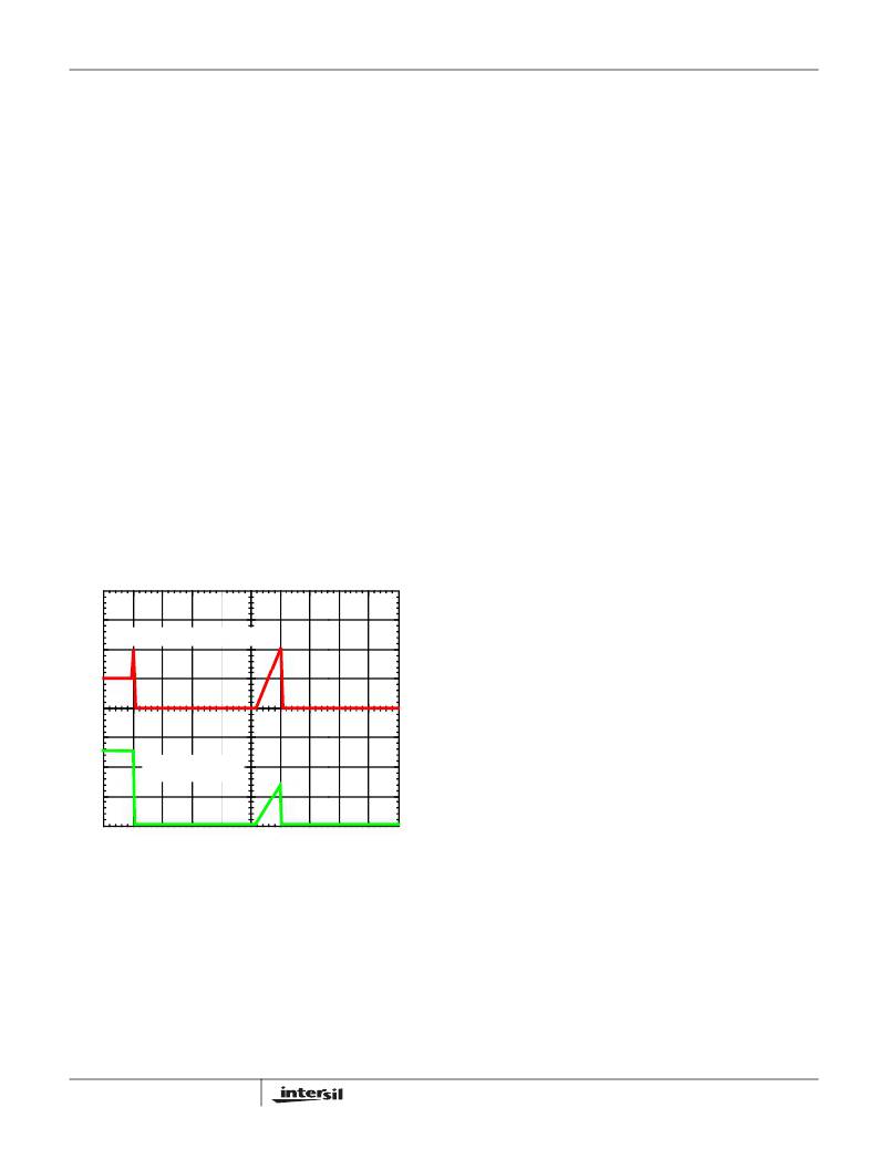
�OUTPUT� CURRENT,� 50A/DIV�
�0A�
�OUTPUT� VOLTAGE,�
�500mV/DIV�
�In� individual� overcurrent� protection� mode,� the� ISL6561�
�continuously� compares� the� current� of� each� channel� with� the�
�same� 100� μ� A� reference� current.� If� any� channel� current�
�exceeds� the� reference� current� continuously� for� eight�
�consecutive� cycles,� the� comparator� triggers� the� converter� to�
�shutdown.�
�At� the� beginning� of� overcurrent� shutdown,� the� controller�
�places� all� PWM� signals� in� a� high-impedance� state�
�commanding� the� Intersil� MOSFET� driver� ICs� to� turn� off� both�
�upper� and� lower� MOSFETs.� The� system� remains� in� this�
�state� a� period� of� 4096� switching� cycles.� If� the� controller� is� still�
�enabled� at� the� end� of� this� wait� period,� it� will� attempt� a� soft�
�start.� If� the� fault� remains,� trip-retry� cycles� continue�
�indefinitely� (as� shown� in� Figure� 12)� until� either� controller� is�
�disabled� or� the� fault� is� cleared.� Note� that� the� energy�
�delivered� during� trip-retry� cycling� is� much� less� than� during�
�full-load� operation,� so� there,� there� is� no� thermal� hazard�
�during� this� kind� of� operation.�
�General� Design� Guide�
�This� design� guide� is� intended� to� provide� a� high-level�
�explanation� of� the� steps� necessary� to� create� a� multi-phase�
�power� converter.� It� is� assumed� that� the� reader� is� familiar� with�
�many� of� the� basic� skills� and� techniques� referenced� below.� In�
�addition� to� this� guide,� Intersil� provides� complete� reference�
�designs� that� include� schematics,� bills� of� materials,� and�
�example� board� layouts� for� all� common� microprocessor�
�applications.�
�Power� Stages�
�The� first� step� in� designing� a� multi-phase� converter� is� to�
�determine� the� number� of� phases.� This� determination�
�depends� heavily� on� the� cost� analysis� which� in� turn� depends�
�on� system� constraints� that� differ� from� one� design� to� the� next.�
�Principally,� the� designer� will� be� concerned� with� whether�
�components� can� be� mounted� on� both� sides� of� the� circuit�
�board;� whether� through-hole� components� are� permitted;� and�
�the� total� board� space� available� for� power-supply� circuitry.�
�Generally� speaking,� the� most� economical� solutions� are�
�those� in� which� each� phase� handles� between� 15� and� 20A.� All�
�surface-mount� designs� will� tend� toward� the� lower� end� of� this�
�current� range.� If� through-hole� MOSFETs� and� inductors� can�
�0V�
�2ms/DIV�
�be� used,� higher� per-phase� currents� are� possible.� In� cases�
�where� board� space� is� the� limiting� constraint,� current� may� be�
�FIGURE� 12.� OVERCURRENT� BEHAVIOR� IN� HICCUP� MODE.�
�F� SW� =� 500kHz�
�In� instantaneous� protection� mode,� the� ISL6561� takes�
�advantage� of� the� proportionality� between� the� load� current�
�and� the� average� current,� I� AVG� to� detect� an� overcurrent�
�condition.� See� the� Channel-Current� Balance� section� for�
�more� detail� on� how� the� average� current� is� measured.� The�
�average� current� is� continually� compared� with� a� constant�
�100� μ� A� reference� current� as� shown� in� Figure� 11.� Once� the�
�average� current� exceeds� the� reference� current,� a� comparator�
�triggers� the� converter� to� shutdown.�
�19�
�pushed� above� 30A� per� phase,� but� these� designs� require�
�heat� sinks� and� forced� air� to� cool� the� MOSFETs,� inductors�
�and� heat-dissipating� surfaces.�
�MOSFETs�
�The� choice� of� MOSFETs� depends� on� the� current� each�
�MOSFET� will� be� required� to� conduct;� the� switching� frequency;�
�the� capability� of� the� MOSFETs� to� dissipate� heat;� and� the�
�availability� and� nature� of� heat� sinking� and� air� flow.�
�FN9098.5�
�May� 12,� 2005�
�相关PDF资料 |
PDF描述 |
|---|---|
| X40014V8I-CT1 | IC VOLTAGE MONITOR DUAL 8-TSSOP |
| ISL6561CRZ | IC CTRLR PWM MULTIPHASE 40-QFN |
| X40014V8I-C | IC VOLTAGE MONITOR DUAL 8-TSSOP |
| ECC60DREN-S13 | CONN EDGECARD 120POS .100 EXTEND |
| ABM22DRSH | CONN EDGECARD 44POS DIP .156 SLD |
相关代理商/技术参数 |
参数描述 |
|---|---|
| ISL6561CRZA-T | 功能描述:IC CTRLR PWM MULTIPHASE 40-QFN RoHS:是 类别:集成电路 (IC) >> PMIC - 稳压器 - 专用型 系列:- 标准包装:43 系列:- 应用:控制器,Intel VR11 输入电压:5 V ~ 12 V 输出数:1 输出电压:0.5 V ~ 1.6 V 工作温度:-40°C ~ 85°C 安装类型:表面贴装 封装/外壳:48-VFQFN 裸露焊盘 供应商设备封装:48-QFN(7x7) 包装:管件 |
| ISL6561CRZR5208 | 制造商:Rochester Electronics LLC 功能描述: 制造商:Intersil Corporation 功能描述: |
| ISL6561CRZ-T | 功能描述:IC CTLR PWM MULTIPHASE 40-QFN RoHS:是 类别:集成电路 (IC) >> PMIC - 稳压器 - 专用型 系列:- 标准包装:2,000 系列:- 应用:控制器,DSP 输入电压:4.5 V ~ 25 V 输出数:2 输出电压:最低可调至 1.2V 工作温度:-40°C ~ 85°C 安装类型:表面贴装 封装/外壳:30-TFSOP(0.173",4.40mm 宽) 供应商设备封装:30-TSSOP 包装:带卷 (TR) |
| ISL6561CRZ-TK | 功能描述:IC CTRLR PWM MULTIPHASE 40-QFN RoHS:是 类别:集成电路 (IC) >> PMIC - 稳压器 - 专用型 系列:- 标准包装:43 系列:- 应用:控制器,Intel VR11 输入电压:5 V ~ 12 V 输出数:1 输出电压:0.5 V ~ 1.6 V 工作温度:-40°C ~ 85°C 安装类型:表面贴装 封装/外壳:48-VFQFN 裸露焊盘 供应商设备封装:48-QFN(7x7) 包装:管件 |
| ISL6561CRZ-TR5208 | 制造商:Rochester Electronics LLC 功能描述: 制造商:Intersil Corporation 功能描述: |
发布紧急采购,3分钟左右您将得到回复。