参数资料
| 型号: | ISL6563IRZ-T |
| 厂商: | Intersil |
| 文件页数: | 8/19页 |
| 文件大小: | 0K |
| 描述: | IC CTRLR PWM MULTIPHASE 24-QFN |
| 产品培训模块: | Solutions for Industrial Control Applications |
| 标准包装: | 6,000 |
| 应用: | 控制器,Intel VRM9,VRM10,AMD Hammer 应用 |
| 输入电压: | 5 V ~ 12 V |
| 输出数: | 1 |
| 输出电压: | 0.8 V ~ 1.85 V |
| 工作温度: | -40°C ~ 85°C |
| 安装类型: | 表面贴装 |
| 封装/外壳: | 24-VFQFN 裸露焊盘 |
| 供应商设备封装: | 24-QFN(4x4) |
| 包装: | 带卷 (TR) |
�� �
�
�ISL6563�
�voltage� droop� characteristic.� Internal� average� channel�
�current� is� fed� into� the� FB� pin;� the� voltage� thus� developed�
�across� R� 1� is� equal� to� the� droop� voltage.�
�To� understand� the� reduction� of� ripple� current� amplitude� in� the�
�multiphase� circuit,� examine� Equation� 5,� which� represents� an�
�individual� channel’s� peak-to-peak� inductor� current.�
�(� V� IN� –� V� OUT� )� ?� V� OUT�
�L� ?� f� S� ?� V�
�Assuming� identical� power� switch� selection� on� the� two�
�channels,� Equation� 4� determines� the� current� fed� out� the� FB�
�pin� for� output� voltage� droop� generation:�
�I� L� ,� PP� =� ----------------------------------------------------------�
�IN�
�(EQ.� 5)�
�R� ISEN�
�r� DS� (� ON� )� ?� I� PHASE�
�I� FB� =� ------------------------------------------------�
�(EQ.� 4)�
�V� IN� and� V� OUT� are� the� input� and� output� voltages,�
�respectively,� L� is� the� single-channel� inductor� value,� and� f� S� is�
�the� switching� frequency.�
�L� ?� f� S� ?� V�
�where,� r� DS(ON)� -� lower� MOSFET/s’� ON� resistance� (@5V)�
�I� PHASE� -� average� phase� current�
�Multiphase� Power� Conversion�
�Multiphase� power� conversion� provides� a� cost-effective�
�power� solution� when� load� currents� are� no� longer� easily�
�supported� by� single-phase� converters.� Although� its� greater�
�complexity� presents� additional� technical� challenges,� the�
�multiphase� approach� offers� cost-saving� advantages� with�
�improved� response� time,� superior� ripple� cancellation,� and�
�thermal� distribution.�
�INTERLEAVING�
�The� switching� of� each� channel� in� an� ISL6563-based�
�converter� is� timed� to� be� symmetrically� out� of� phase� with� the�
�other� channel.� As� a� result,� the� two-phase� converter� has� a�
�combined� ripple� frequency� twice� the� frequency� of� one� of� its�
�phases.� In� addition,� the� peak-to-peak� amplitude� of� the�
�combined� inductor� currents� is� proportionately� reduced.�
�Increased� ripple� frequency� and� lower� ripple� amplitude�
�generally� translate� to� lower� per-channel� inductance� and�
�lower� total� output� capacitance� for� a� given� set� of� performance�
�specifications.�
�The� output� capacitors� conduct� the� ripple� component� of� the�
�inductor� current.� In� the� case� of� multiphase� converters,� the�
�capacitor� current� is� the� sum� of� the� ripple� currents� from� each�
�of� the� individual� channels.� Peak-to-peak� ripple� current,� I� PP� ,�
�decreases� by� an� amount� proportional� to� the� number� of�
�channels.� Output-voltage� ripple� is� a� function� of� capacitance,�
�capacitor� equivalent� series� resistance� (ESR),� and� inductor�
�ripple� current.� Reducing� the� inductor� ripple� current� allows�
�the� designer� to� use� fewer� or� less� costly� output� capacitors�
�(should� output� ripple� be� an� important� design� parameter).�
�(� V� IN� –� N� ?� V� OUT� )� ?� V� OUT� (EQ.� 6)�
�I� PP� =� --------------------------------------------------------------------�
�IN�
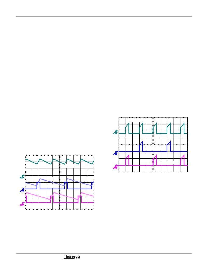
�C� IN� CURRENT�
�Q1 D-S CURRENT�
�Q3 D-S CURRENT�
�I� L1� +� I� L2�
�FIGURE� 3.� INPUT� CAPACITOR� CURRENT� AND� INDIVIDUAL�
�I� L2�
�CHANNEL� CURRENTS� IN� A� 2-PHASE�
�CONVERTER�
�PWM2�
�Another� benefit� of� interleaving� is� the� reduction� of� input� ripple�
�I� L1�
�PWM1�
�FIGURE� 2.� PWM� AND� INDUCTOR-CURRENT� WAVEFORMS�
�FOR� 2-PHASE� CONVERTER�
�Figure� 2� illustrates� the� additive� effect� on� output� ripple�
�frequency.� The� two� channel� currents� (I� L1� and� I� L2� ),� combine�
�to� form� the� AC� ripple� current� and� the� DC� load� current.� The�
�ripple� component� has� two� times� the� ripple� frequency� of� each�
�individual� channel� current.�
�8�
�current.� Input� capacitance� is� determined� in� a� large� part� by�
�the� maximum� input� ripple� current.� Multiphase� topologies� can�
�improve� overall� system� cost� and� size� by� lowering� input� ripple�
�current� and� allowing� the� designer� to� reduce� the� cost� of� input�
�capacitance.� The� example� in� Figure� 3� illustrates� input�
�currents� from� a� two-phase� converter� combining� to� reduce�
�the� total� input� ripple� current.�
��can� be� used� to� determine� the� input-capacitor� RMS� current�
�based� on� load� current� and� duty� cycle.� The� figure� is� provided�
�as� an� aid� in� determining� the� optimal� input� capacitor� solution.�
�FN9126.8�
�June� 10,� 2010�
�相关PDF资料 |
PDF描述 |
|---|---|
| 2510-44K | INDUCTOR RF 6.8UH UNSHIELDED SMD |
| ISL6424ERZ-T | IC REG DUAL LNBP TTL-INP 32-QFN |
| MIC49500-1.2WU | IC REG LDO 1.2V 5A TO-263-7 |
| 2510-42K | INDUCTOR RF 5.6UH UNSHIELDED SMD |
| 2510-40K | INDUCTOR RF 4.7UH UNSHIELDED SMD |
相关代理商/技术参数 |
参数描述 |
|---|---|
| ISL6564ACRZ | 功能描述:IC REG CTRLR BUCK PWM VM 40-QFN RoHS:是 类别:集成电路 (IC) >> PMIC - 稳压器 - DC DC 切换控制器 系列:- 产品培训模块:Lead (SnPb) Finish for COTS Obsolescence Mitigation Program 标准包装:2,500 系列:- PWM 型:电流模式 输出数:1 频率 - 最大:275kHz 占空比:50% 电源电压:18 V ~ 110 V 降压:无 升压:无 回扫:无 反相:无 倍增器:无 除法器:无 Cuk:无 隔离:是 工作温度:-40°C ~ 85°C 封装/外壳:8-SOIC(0.154",3.90mm 宽) 包装:带卷 (TR) |
| ISL6564ACRZ-T | 功能描述:IC REG CTRLR BUCK PWM VM 40-QFN RoHS:是 类别:集成电路 (IC) >> PMIC - 稳压器 - DC DC 切换控制器 系列:- 产品培训模块:Lead (SnPb) Finish for COTS Obsolescence Mitigation Program 标准包装:2,500 系列:- PWM 型:电流模式 输出数:1 频率 - 最大:275kHz 占空比:50% 电源电压:18 V ~ 110 V 降压:无 升压:无 回扫:无 反相:无 倍增器:无 除法器:无 Cuk:无 隔离:是 工作温度:-40°C ~ 85°C 封装/外壳:8-SOIC(0.154",3.90mm 宽) 包装:带卷 (TR) |
| ISL6564AIRZ | 功能描述:IC REG CTRLR BUCK PWM VM 40-QFN RoHS:是 类别:集成电路 (IC) >> PMIC - 稳压器 - DC DC 切换控制器 系列:- 产品培训模块:Lead (SnPb) Finish for COTS Obsolescence Mitigation Program 标准包装:2,500 系列:- PWM 型:电流模式 输出数:1 频率 - 最大:275kHz 占空比:50% 电源电压:18 V ~ 110 V 降压:无 升压:无 回扫:无 反相:无 倍增器:无 除法器:无 Cuk:无 隔离:是 工作温度:-40°C ~ 85°C 封装/外壳:8-SOIC(0.154",3.90mm 宽) 包装:带卷 (TR) |
| ISL6564AIRZ-T | 功能描述:IC REG CTRLR BUCK PWM VM 40-QFN RoHS:是 类别:集成电路 (IC) >> PMIC - 稳压器 - DC DC 切换控制器 系列:- 产品培训模块:Lead (SnPb) Finish for COTS Obsolescence Mitigation Program 标准包装:2,500 系列:- PWM 型:电流模式 输出数:1 频率 - 最大:275kHz 占空比:50% 电源电压:18 V ~ 110 V 降压:无 升压:无 回扫:无 反相:无 倍增器:无 除法器:无 Cuk:无 隔离:是 工作温度:-40°C ~ 85°C 封装/外壳:8-SOIC(0.154",3.90mm 宽) 包装:带卷 (TR) |
| ISL6564CR | 功能描述:IC REG CTRLR BUCK PWM VM 40-QFN RoHS:否 类别:集成电路 (IC) >> PMIC - 稳压器 - DC DC 切换控制器 系列:- 标准包装:4,000 系列:- PWM 型:电压模式 输出数:1 频率 - 最大:1.5MHz 占空比:66.7% 电源电压:4.75 V ~ 5.25 V 降压:是 升压:无 回扫:无 反相:无 倍增器:无 除法器:无 Cuk:无 隔离:无 工作温度:-40°C ~ 85°C 封装/外壳:40-VFQFN 裸露焊盘 包装:带卷 (TR) |
发布紧急采购,3分钟左右您将得到回复。