- 您现在的位置:买卖IC网 > PDF目录15062 > ISL6565BCV (Intersil)IC REG CTRLR BUCK PWM VM 28TSSOP PDF资料下载
参数资料
| 型号: | ISL6565BCV |
| 厂商: | Intersil |
| 文件页数: | 20/28页 |
| 文件大小: | 0K |
| 描述: | IC REG CTRLR BUCK PWM VM 28TSSOP |
| 标准包装: | 50 |
| PWM 型: | 电压模式 |
| 输出数: | 1 |
| 频率 - 最大: | 1.5MHz |
| 占空比: | 66.7% |
| 电源电压: | 4.75 V ~ 5.25 V |
| 降压: | 是 |
| 升压: | 无 |
| 回扫: | 无 |
| 反相: | 无 |
| 倍增器: | 无 |
| 除法器: | 无 |
| Cuk: | 无 |
| 隔离: | 无 |
| 工作温度: | 0°C ~ 105°C |
| 封装/外壳: | 28-TSSOP(0.173",4.40mm 宽) |
| 包装: | 管件 |
第1页第2页第3页第4页第5页第6页第7页第8页第9页第10页第11页第12页第13页第14页第15页第16页第17页第18页第19页当前第20页第21页第22页第23页第24页第25页第26页第27页第28页
�� �
�
�ISL6565A,� ISL6565B�
�P� UP� ,� 1� ≈� V� IN� ?� ------� +� ---------� ?� ?� ----� 1� ?� f� S�
�the� required� time� for� this� commutation� is� t� 1� and� the�
�approximated� associated� power� loss� is� P� UP,1� .�
�I� M� I� PP� ?� t� ?�
�?� N� 2� ?� ?� 2� ?�
�(EQ.� 22)�
�V� IN�
�CHANNEL� N�
�UPPER� MOSFET�
�I� L�
�At� turn� on,� the� upper� MOSFET� begins� to� conduct� and� this�
�transition� occurs� over� a� time� t� 2� .� In� Equation� 23,� the�
�approximate� power� loss� is� P� UP,2� .�
�ISEN(n)�
�R� ISEN�
�P� UP� ,� 2� ≈� V� IN� ?� ------� –� ---------� ?� ?� ----� 2� ?� f� S�
�L� DS� (� ON� )�
�?� I� M� I� PP� ?� ?� t� ?�
�?� N� 2� ?� ?� 2� ?�
�(EQ.� 23)�
�ISL6565A�
�-�
�+�
�I�
�r�
�CHANNEL� N�
�A� third� component� involves� the� lower� MOSFET’s� reverse-�
�recovery� charge,� Q� rr� .� Since� the� inductor� current� has� fully�
�commutated� to� the� upper� MOSFET� before� the� lower-�
�MOSFET’s� body� diode� can� recover� all� of� Q� rr� ,� it� is� conducted�
�through� the� upper� MOSFET� across� VIN.� The� power�
�LOWER� MOSFET�
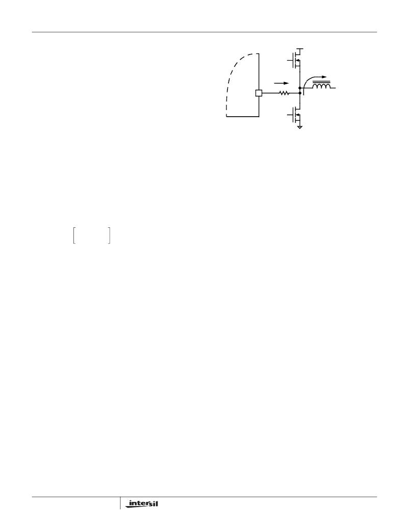
�FIGURE� 15.� ISL6565A� INTERNAL� AND� EXTERNAL� CURRENT-�
�SENSING� CIRCUITRY�
�Select� values� for� these� resistors� based� on� the� room�
�dissipated� as� a� result� is� P� UP,3� .�
�P� UP� ,� 3� =� V� IN� Q� rr� f� S�
�(EQ.� 24)�
�temperature� r� DS(ON)� of� the� lower� MOSFETs;� the� full-load�
�operating� current,� I� FL� ;� and� the� number� of� phases,� N� using�
�Equation� 26.�
�R� ISEN� =� -----------------------� )�
�I� FL�
�Finally,� the� resistive� part� of� the� upper� MOSFETs� is� given� in�
�Equation� 25� as� P� UP,4� .�
�r� DS� (� ON�
�70� ×� 10� –� 6�
�--------�
�N�
�(EQ.� 26)�
�I� PP2�
�?� I� M� ?�
�P� UP� ,� 4� ≈� r� DS� (� ON� )� ?� ------� ?� d� +� ----------�
�2�
�?� N� ?� 12�
�(EQ.� 25)�
�In� certain� circumstances,� it� may� be� necessary� to� adjust� the�
�value� of� one� or� more� ISEN� resistor.� When� the� components� of�
�one� or� more� channels� are� inhibited� from� effectively� dissipating�
�The� total� power� dissipated� by� the� upper� MOSFET� at� full� load�
�can� now� be� approximated� as� the� summation� of� the� results�
�from� Equations� 22,� 23,� 24� and� 25.� Since� the� power�
�equations� depend� on� MOSFET� parameters,� choosing� the�
�correct� MOSFETs� can� be� an� iterative� process� involving�
�repetitive� solutions� to� the� loss� equations� for� different�
�their� heat� so� that� the� affected� channels� run� hotter� than�
�desired,� choose� new,� smaller� values� of� R� ISEN� for� the� affected�
�phases� (see� the� section� entitled� Voltage� Regulation� ).� Choose�
�R� ISEN,2� in� proportion� to� the� desired� decrease� in� temperature�
�rise� in� order� to� cause� proportionally� less� current� to� flow� in� the�
�hotter� phase.�
�R� ISEN� ,� 2� =� R� ISEN� ----------� 2�
�MOSFETs� and� different� switching� frequencies.�
�Current� Sensing� Component� Selection�
�?� T�
�?� T� 1�
�(EQ.� 27)�
�The� ISL6565A� supports� MOSFET� r� DS(ON)� current� sensing,�
�while� the� ISL6565B� uses� inductor� DCR� current� sensing.� The�
�procedures� for� choosing� the� components� for� each� method� of�
�current� sensing� are� very� different� and� are� described� in� the�
�next� two� sections.�
�MOSFET� r� DS(ON)� SENSING� (ISL6565A� ONLY)�
�The� ISL6565A� senses� the� channel� load� current� by� sampling�
�the� voltage� across� the� lower� MOSFET� r� DS(ON)� ,� as� shown� in�
�Figure� 15.� The� ISEN� pins� are� denoted� ISEN1,� ISEN2,� and�
�ISEN3.� The� resistors� connected� between� these� pins� and� the�
�respective� phase� nodes� determine� the� gains� in� the� load-line�
�regulation� loop� and� the� channel-current� balance� loop� as� well�
�as� setting� the� overcurrent� trip� point.�
�20�
�In� Equation� 27,� make� sure� that� ?� T� 2� is� the� desired� temperature�
�rise� above� the� ambient� temperature,� and� ?� T� 1� is� the� measured�
�temperature� rise� above� the� ambient� temperature.� While� a�
�single� adjustment� according� to� Equation� 27� is� usually�
�sufficient,� it� may� occasionally� be� necessary� to� adjust� R� ISEN�
�two� or� more� times� to� achieve� optimal� thermal� balance�
�between� all� channels.�
�INDUCTOR� DCR� SENSING� (ISL6565B� ONLY)�
�The� ISL6565B� senses� the� channel� load� current� by� sampling�
�the� voltage� across� the� output� inductor� DCR,� as� described� in�
�the� Current� Sensing� section.� As� Figure� 16� illustrates,� an� R-C�
�network� across� the� inductor� is� required� to� sense� the� channel�
�current� accurately.�
�FN9135.4�
�December� 1,� 2005�
�相关PDF资料 |
PDF描述 |
|---|---|
| VI-JTR-EY-F1 | CONVERTER MOD DC/DC 7.5V 50W |
| VI-B5M-EV-F4 | CONVERTER MOD DC/DC 10V 150W |
| ISL6551IR | IC REG CTRLR FLYBACK PWM 28-QFN |
| VI-JTM-EY-F4 | CONVERTER MOD DC/DC 10V 50W |
| B82462G2334M | INDUCTOR POWER 330UH 220MA SMD |
相关代理商/技术参数 |
参数描述 |
|---|---|
| ISL6565BCV-T | 功能描述:IC REG CTRLR BUCK PWM VM 28TSSOP RoHS:否 类别:集成电路 (IC) >> PMIC - 稳压器 - DC DC 切换控制器 系列:- 标准包装:2,500 系列:- PWM 型:电流模式 输出数:1 频率 - 最大:500kHz 占空比:100% 电源电压:8.2 V ~ 30 V 降压:无 升压:无 回扫:是 反相:无 倍增器:无 除法器:无 Cuk:无 隔离:是 工作温度:0°C ~ 70°C 封装/外壳:8-DIP(0.300",7.62mm) 包装:管件 产品目录页面:1316 (CN2011-ZH PDF) |
| ISL6565BCVZ | 功能描述:IC REG CTRLR BUCK PWM VM 28TSSOP RoHS:是 类别:集成电路 (IC) >> PMIC - 稳压器 - DC DC 切换控制器 系列:- 产品培训模块:Lead (SnPb) Finish for COTS Obsolescence Mitigation Program 标准包装:2,500 系列:- PWM 型:电流模式 输出数:1 频率 - 最大:275kHz 占空比:50% 电源电压:18 V ~ 110 V 降压:无 升压:无 回扫:无 反相:无 倍增器:无 除法器:无 Cuk:无 隔离:是 工作温度:-40°C ~ 85°C 封装/外壳:8-SOIC(0.154",3.90mm 宽) 包装:带卷 (TR) |
| ISL6565BCVZ-T | 功能描述:IC REG CTRLR BUCK PWM VM 28TSSOP RoHS:是 类别:集成电路 (IC) >> PMIC - 稳压器 - DC DC 切换控制器 系列:- 产品培训模块:Lead (SnPb) Finish for COTS Obsolescence Mitigation Program 标准包装:2,500 系列:- PWM 型:电流模式 输出数:1 频率 - 最大:275kHz 占空比:50% 电源电压:18 V ~ 110 V 降压:无 升压:无 回扫:无 反相:无 倍增器:无 除法器:无 Cuk:无 隔离:是 工作温度:-40°C ~ 85°C 封装/外壳:8-SOIC(0.154",3.90mm 宽) 包装:带卷 (TR) |
| ISL6566ACRZ | 功能描述:IC CTRLR PWM 3PHASE BUCK 40-QFN RoHS:是 类别:集成电路 (IC) >> PMIC - 稳压器 - 专用型 系列:- 标准包装:43 系列:- 应用:控制器,Intel VR11 输入电压:5 V ~ 12 V 输出数:1 输出电压:0.5 V ~ 1.6 V 工作温度:-40°C ~ 85°C 安装类型:表面贴装 封装/外壳:48-VFQFN 裸露焊盘 供应商设备封装:48-QFN(7x7) 包装:管件 |
| ISL6566ACRZ-T | 功能描述:IC CTRLR PWM 3PHASE BUCK 40-QFN RoHS:是 类别:集成电路 (IC) >> PMIC - 稳压器 - 专用型 系列:- 标准包装:43 系列:- 应用:控制器,Intel VR11 输入电压:5 V ~ 12 V 输出数:1 输出电压:0.5 V ~ 1.6 V 工作温度:-40°C ~ 85°C 安装类型:表面贴装 封装/外壳:48-VFQFN 裸露焊盘 供应商设备封装:48-QFN(7x7) 包装:管件 |
发布紧急采购,3分钟左右您将得到回复。