- 您现在的位置:买卖IC网 > PDF目录15170 > ISL6565BCVZ (Intersil)IC REG CTRLR BUCK PWM VM 28TSSOP PDF资料下载
参数资料
| 型号: | ISL6565BCVZ |
| 厂商: | Intersil |
| 文件页数: | 10/28页 |
| 文件大小: | 0K |
| 描述: | IC REG CTRLR BUCK PWM VM 28TSSOP |
| 标准包装: | 500 |
| PWM 型: | 电压模式 |
| 输出数: | 1 |
| 频率 - 最大: | 1.5MHz |
| 占空比: | 66.7% |
| 电源电压: | 4.75 V ~ 5.25 V |
| 降压: | 是 |
| 升压: | 无 |
| 回扫: | 无 |
| 反相: | 无 |
| 倍增器: | 无 |
| 除法器: | 无 |
| Cuk: | 无 |
| 隔离: | 无 |
| 工作温度: | 0°C ~ 105°C |
| 封装/外壳: | 28-TSSOP(0.173",4.40mm 宽) |
| 包装: | 管件 |
第1页第2页第3页第4页第5页第6页第7页第8页第9页当前第10页第11页第12页第13页第14页第15页第16页第17页第18页第19页第20页第21页第22页第23页第24页第25页第26页第27页第28页
�� �
�
�ISL6565A,� ISL6565B�
�(� V� IN� –� V� OUT� )� V� OUT� (EQ.� 1)�
�Operation�
�Multi-Phase� Power� Conversion�
�Microprocessor� load� current� profiles� have� changed� to� the�
�point� that� the� advantages� of� multi-phase� power� conversion�
�are� impossible� to� ignore.� The� technical� challenges�
�associated� with� producing� a� single-phase� converter� that� is�
�both� cost-effective� and� thermally� viable� have� forced� a�
�change� to� the� cost-saving� approach� of� multi-phase.� The�
�ISL6565A,� ISL6565B� controller� helps� simplify�
�implementation� by� integrating� vital� functions� and� requiring�
�minimal� output� components.� The� block� diagrams� on� pages� 3�
�and� 4� provide� top� level� views� of� multi-phase� power�
�conversion� using� the� ISL6565A� and� ISL6565B� controllers.�
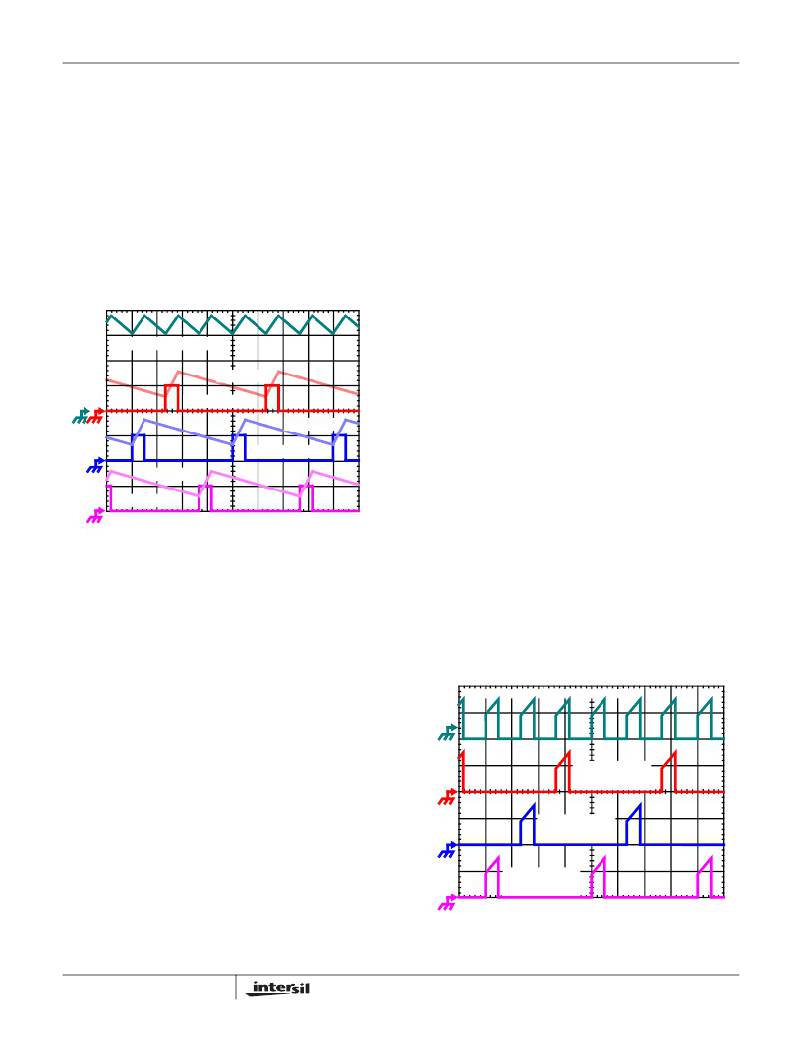
�IL1� +� IL2� +� IL3,� 7A/DIV�
�IL3, 7A/DIV�
�To� understand� the� reduction� of� ripple� current� amplitude� in� the�
�multi-phase� circuit,� examine� the� equation� representing� an�
�individual� channel’s� peak-to-peak� inductor� current.�
�I� PP� =� ------------------------------------------------------�
�L� f� S� V� IN�
�In� Equation� 1,� V� IN� and� V� OUT� are� the� input� and� output�
�voltages� respectively,� L� is� the� single-channel� inductor� value,�
�and� f� S� is� the� switching� frequency.�
�The� output� capacitors� conduct� the� ripple� component� of� the�
�inductor� current.� In� the� case� of� multi-phase� converters,� the�
�capacitor� current� is� the� sum� of� the� ripple� currents� from� each�
�of� the� individual� channels.� Compare� Equation� 1� to� the�
�expression� for� the� peak-to-peak� current� after� the� summation�
�of� N� symmetrically� phase-shifted� inductor� currents� in�
�Equation� 2.� Peak-to-peak� ripple� current� decreases� by� an�
�amount� proportional� to� the� number� of� channels.� Output-�
�voltage� ripple� is� a� function� of� capacitance,� capacitor�
�equivalent� series� resistance� (ESR),� and� inductor� ripple�
�current.� Reducing� the� inductor� ripple� current� allows� the�
�designer� to� use� fewer� or� less� costly� output� capacitors.�
�(� V� IN� –� N� V� OUT� )� V� OUT�
�I� C� ,� PP� =� ------------------------------------------------------------�
�PWM3, 5V/DIV�
�IL2, 7A/DIV�
�L� f� S� V� IN�
�(EQ.� 2)�
�PWM2, 5V/DIV�
�IL1, 7A/DIV�
�PWM1, 5V/DIV�
�1� μ� s/DIV�
�FIGURE� 1.� PWM� AND� INDUCTOR-CURRENT� WAVEFORMS�
�FOR� 3-PHASE� CONVERTER�
�Interleaving�
�The� switching� of� each� channel� in� a� multi-phase� converter� is�
�timed� to� be� symmetrically� out� of� phase� with� each� of� the� other�
�channels.� In� a� 3-phase� converter,� each� channel� switches� 1/3�
�cycle� after� the� previous� channel� and� 1/3� cycle� before� the�
�following� channel.� As� a� result,� the� three-phase� converter� has�
�a� combined� ripple� frequency� three� times� greater� than� the�
�ripple� frequency� of� any� one� phase.� In� addition,� the� peak-to-�
�peak� amplitude� of� the� combined� inductor� currents� is� reduced�
�in� proportion� to� the� number� of� phases� (Equations� 1� and� 2).�
�Increased� ripple� frequency� and� lower� ripple� amplitude� mean�
�that� the� designer� can� use� less� per-channel� inductance� and�
�lower� total� output� capacitance� for� any� performance�
�specification.�
�Figure� 1� illustrates� the� multiplicative� effect� on� output� ripple�
�frequency.� The� three� channel� currents� (IL1,� IL2,� and� IL3)�
�combine� to� form� the� AC� ripple� current� and� the� DC� load�
�current.� The� ripple� component� has� three� times� the� ripple�
�frequency� of� each� individual� channel� current.� Each� PWM�
�pulse� is� terminated� 1/3� of� a� cycle� after� the� PWM� pulse� of� the�
�previous� phase.� The� peak-to-peak� current� for� each� phase� is�
�about� 7A,� and� the� DC� components� of� the� inductor� currents�
�combine� to� feed� the� load.�
�10�
�Another� benefit� of� interleaving� is� to� reduce� input� ripple�
�current.� Input� capacitance� is� determined� in� part� by� the�
�maximum� input� ripple� current.� Multi-phase� topologies� can�
�improve� overall� system� cost� and� size� by� lowering� input� ripple�
�current� and� allowing� the� designer� to� reduce� the� cost� of� input�
�capacitance.� The� example� in� Figure� 2� illustrates� input�
�currents� from� a� three-phase� converter� combining� to� reduce�
�the� total� input� ripple� current.�
�The� converter� depicted� in� Figure� 2� delivers� 1.5V� to� a� 36A� load�
�from� a� 12V� input.� The� RMS� input� capacitor� current� is� 5.9A.�
�Compare� this� to� a� single-phase� converter� also� stepping� down�
�12V� to� 1.5V� at� 36A.� The� single-phase� converter� has� 11.9A�
�RMS� input� capacitor� current.� The� single-phase� converter�
�must� use� an� input� capacitor� bank� with� twice� the� RMS� current�
�capacity� as� the� equivalent� three-phase� converter.�
�INPUT-CAPACITOR CURRENT, 10A/DIV�
�CHANNEL� 3�
�INPUT� CURRENT�
�10A/DIV�
�CHANNEL� 2�
�INPUT� CURRENT�
�10A/DIV�
�CHANNEL� 1�
�INPUT� CURRENT�
�10A/DIV�
�1� μ� s/DIV�
�FIGURE� 2.� CHANNEL� INPUT� CURRENTS� AND� INPUT-�
�CAPACITOR� RMS� CURRENT� FOR� 3-PHASE�
�CONVERTER�
�FN9135.4�
�December� 1,� 2005�
�相关PDF资料 |
PDF描述 |
|---|---|
| ISL6565BCRZ | IC REG CTRLR BUCK PWM VM 28-QFN |
| ISL6565ACVZ | IC REG CTRLR BUCK PWM VM 28TSSOP |
| ISL6755AAZA-T | IC REG CTRLR PWM CM/VM 20-QSOP |
| ISL6306IRZ-T | IC REG CTRLR BUCK PWM VM 40-QFN |
| ISL6726AAZ-T | IC REG CTRLR ISO PWM CM 20-QSOP |
相关代理商/技术参数 |
参数描述 |
|---|---|
| ISL6565BCVZ-T | 功能描述:IC REG CTRLR BUCK PWM VM 28TSSOP RoHS:是 类别:集成电路 (IC) >> PMIC - 稳压器 - DC DC 切换控制器 系列:- 产品培训模块:Lead (SnPb) Finish for COTS Obsolescence Mitigation Program 标准包装:2,500 系列:- PWM 型:电流模式 输出数:1 频率 - 最大:275kHz 占空比:50% 电源电压:18 V ~ 110 V 降压:无 升压:无 回扫:无 反相:无 倍增器:无 除法器:无 Cuk:无 隔离:是 工作温度:-40°C ~ 85°C 封装/外壳:8-SOIC(0.154",3.90mm 宽) 包装:带卷 (TR) |
| ISL6566ACRZ | 功能描述:IC CTRLR PWM 3PHASE BUCK 40-QFN RoHS:是 类别:集成电路 (IC) >> PMIC - 稳压器 - 专用型 系列:- 标准包装:43 系列:- 应用:控制器,Intel VR11 输入电压:5 V ~ 12 V 输出数:1 输出电压:0.5 V ~ 1.6 V 工作温度:-40°C ~ 85°C 安装类型:表面贴装 封装/外壳:48-VFQFN 裸露焊盘 供应商设备封装:48-QFN(7x7) 包装:管件 |
| ISL6566ACRZ-T | 功能描述:IC CTRLR PWM 3PHASE BUCK 40-QFN RoHS:是 类别:集成电路 (IC) >> PMIC - 稳压器 - 专用型 系列:- 标准包装:43 系列:- 应用:控制器,Intel VR11 输入电压:5 V ~ 12 V 输出数:1 输出电压:0.5 V ~ 1.6 V 工作温度:-40°C ~ 85°C 安装类型:表面贴装 封装/外壳:48-VFQFN 裸露焊盘 供应商设备封装:48-QFN(7x7) 包装:管件 |
| ISL6566AIRZ | 功能描述:IC CTRLR PWM 3PHASE BUCK 40-QFN RoHS:是 类别:集成电路 (IC) >> PMIC - 稳压器 - 专用型 系列:- 标准包装:43 系列:- 应用:控制器,Intel VR11 输入电压:5 V ~ 12 V 输出数:1 输出电压:0.5 V ~ 1.6 V 工作温度:-40°C ~ 85°C 安装类型:表面贴装 封装/外壳:48-VFQFN 裸露焊盘 供应商设备封装:48-QFN(7x7) 包装:管件 |
| ISL6566AIRZ-T | 功能描述:IC CTRLR PWM 3PHASE BUCK 40-QFN RoHS:是 类别:集成电路 (IC) >> PMIC - 稳压器 - 专用型 系列:- 标准包装:43 系列:- 应用:控制器,Intel VR11 输入电压:5 V ~ 12 V 输出数:1 输出电压:0.5 V ~ 1.6 V 工作温度:-40°C ~ 85°C 安装类型:表面贴装 封装/外壳:48-VFQFN 裸露焊盘 供应商设备封装:48-QFN(7x7) 包装:管件 |
发布紧急采购,3分钟左右您将得到回复。