- 您现在的位置:买卖IC网 > PDF目录15196 > ISL8104IBZ (Intersil)IC REG CTRLR BUCK PWM VM 14-SOIC PDF资料下载
参数资料
| 型号: | ISL8104IBZ |
| 厂商: | Intersil |
| 文件页数: | 7/14页 |
| 文件大小: | 0K |
| 描述: | IC REG CTRLR BUCK PWM VM 14-SOIC |
| 标准包装: | 500 |
| PWM 型: | 电压模式 |
| 输出数: | 1 |
| 频率 - 最大: | 1.5MHz |
| 占空比: | 100% |
| 电源电压: | 7.6 V ~ 15.4 V |
| 降压: | 是 |
| 升压: | 无 |
| 回扫: | 无 |
| 反相: | 无 |
| 倍增器: | 无 |
| 除法器: | 无 |
| Cuk: | 无 |
| 隔离: | 无 |
| 工作温度: | -40°C ~ 85°C |
| 封装/外壳: | 14-SOIC(0.154",3.90mm 宽) |
| 包装: | 管件 |
�� �
�
�ISL8104�
�reference� input� (positive� terminal� of� error� amp)� from� GND� to�
�VREF� (0.597V� nominal).� If� the� ISL8104� is� utilizing� an�
�externally� supplied� reference,� when� the� voltage� on� the� SS� pin�
�reaches� 1V,� the� internal� reference� input� (into� the� error� amp)�
�ramps� from� GND� to� the� externally� supplied� reference� at� the�
�same� rate� as� the� voltage� on� the� SS� pin.� Figure� 3� shows� a�
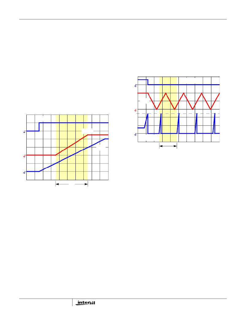
�typical� soft-start� interval.� The� rise� time� of� the� output� voltage� is,�
�therefore,� dependent� upon� the� value� of� the� soft-start�
�capacitor,� C� SS� .� If� the� internal� reference� is� used,� then� the�
�soft-start� capacitance� value� can� be� calculated� through�
�Equation� 3:�
�Oscillator�
�The� oscillator� is� a� triangular� waveform,� providing� for� leading�
�and� falling� edge� modulation.� The� peak-to-peak� of� the� ramp�
�amplitude� is� set� at� 1.9V� and� varies� as� a� function� of� frequency.�
�At� 50kHz� the� peak� to� peak� amplitude� is� approximately� 1.8V�
�while� at� 1.5MHz� it� is� approximately� 2.2V.� In� the� event� the�
�regulator� operates� at� 100%� duty� cycle� for� 64� clock� cycles� an�
�automatic� boot� cap� refresh� circuit� will� activate� turning� on�
�BGATE� for� approximately� 1/2� of� a� clock� cycle.�
�Overcurrent� Protection�
�C� SS� =� ----------------------------�
�C� SS� =� ----------------------------�
�30� μ� A� ?� t� SS�
�2V�
�If� an� external� reference� is� used� then� the� soft-start�
�capacitance� can� be� calculated� through� Equation� 4:�
�30� μ� A� ?� t� SS�
�V� REFEXT�
�(EQ.� 3)�
�(EQ.� 4)�
�V� SS�
�V� SSDONE�
�I� OCP�
�V� EN�
�V� OUT�
�I� LOAD�
�V� SS�
�t� SS�
�FIGURE� 3.� TYPICAL� SOFT-START� INTERVAL�
�Prebiased� Load� Start-up�
�Drivers� are� held� in� tri-state� (TGATE� pulled� to� LX,� BGATE�
�pulled� to� PGND)� at� the� beginning� of� a� soft-start� cycle� until�
�two� PWM� pulses� are� detected.� The� bottom-side� MOSFET� is�
�turned� on� first� to� provide� for� charging� of� the� bootstrap�
�capacitor.� This� method� of� driver� activation� provides� support�
�for� start-up� into� prebiased� loads� by� not� activating� the� drivers�
�until� the� control� loop� has� entered� its� linear� region,� thereby�
�substantially� reducing� output� transients� that� would� otherwise�
�occur� had� the� drivers� been� activated� at� the� beginning� of� the�
�soft-start� cycle.�
�SSDONE�
�Soft-start� done� is� only� available� in� the� 16� Ld� QFN� packaging�
�option� of� the� ISL8104.� When� the� soft-start� pin� reaches� 4V,� an�
�open� drain� signal� is� provided� to� support� sequencing�
�requirements.� SSDONE� is� deasserted� by� disabling� of� the� part,�
�including� pulling� SS� low,� and� by� POR� and� OCP� events.�
�7�
�t� HICCUP�
�FIGURE� 4.� TYPICAL� OVERCURRENT� PROTECTION�
�The� OCP� function� is� enabled� with� the� drivers� at� start-up.�
�OCP� is� implemented� via� a� resistor� (R� TSOC� )� and� a� capacitor�
�(C� TSOC� )� connecting� the� TSOC� pin� and� the� drain� of� the�
�top-side� MOSEFT.� An� internal� 200� m� A� current� source�
�develops� a� voltage� across� R� TSOC� ,� which� is� then� compared�
�with� the� voltage� developed� across� the� top-side� MOSFET� at�
�turn� on� as� measured� at� the� LX� pin.� When� the� voltage� drop�
�across� the� MOSFET� exceeds� the� voltage� drop� across� the�
�resistor,� a� sourcing� OCP� event� occurs.� C� TSOC� is� placed� in�
�parallel� with� R� TSOC� to� smooth� the� voltage� across� R� TSOC� in�
�the� presence� of� switching� noise� on� the� input� bus.�
�A� 120ns� blanking� period� is� used� to� reduce� the� current�
�sampling� error� due� to� leading-edge� switching� noise.� An�
�additional� simultaneous� 120ns� low� pass� filter� is� used� to�
�further� reduce� measurement� error� due� to� noise.�
�OCP� faults� cause� the� regulator� to� disable� (top-� and�
�bottom-side� drives� disabled,� SSDONE� pulled� low,� soft-start�
�capacitor� discharged)� itself� for� a� fixed� period� of� time,� after�
�which� a� normal� soft-start� sequence� is� initiated.� If� the� voltage�
�on� the� SS� pin� is� already� at� 4V� and� an� OCP� is� detected,� a�
�30� μ� A� current� sink� is� immediately� applied� to� the� SS� pin.� If� an�
�OCP� is� detected� during� soft-start,� the� 30μA� current� sink� will�
�not� be� applied� until� the� voltage� on� the� SS� pin� has� reached� 4V.�
�This� current� sink� discharges� the� C� SS� capacitor� in� a� linear�
�fashion.� Once� the� voltage� on� the� SS� pin� has� reached�
�approximately� 0V,� the� normal� soft-start� sequence� is� initiated.� If�
�the� fault� is� still� present� on� the� subsequent� restart,� the� ISL8104�
�FN9257.2�
�March� 7,� 2008�
�相关PDF资料 |
PDF描述 |
|---|---|
| ISL8843MBZ | IC REG CTRLR BST FLYBK ISO 8SOIC |
| ACC17DREF | CONN EDGECARD 34POS .100 EYELET |
| VE-J4P-EW-F4 | CONVERTER MOD DC/DC 13.8V 100W |
| B41042A5108M | 1000UF 25V 12.5X25 SINGLE END |
| ISL8843AUZ | IC REG CTRLR BST FLYBK ISO 8MSOP |
相关代理商/技术参数 |
参数描述 |
|---|---|
| ISL8104IBZ | 制造商:Intersil Corporation 功能描述:Pulse Width Modulation (PWM) Controller |
| ISL8104IBZ-T | 功能描述:IC REG CTRLR BUCK PWM VM 14-SOIC RoHS:是 类别:集成电路 (IC) >> PMIC - 稳压器 - DC DC 切换控制器 系列:- 产品培训模块:Lead (SnPb) Finish for COTS Obsolescence Mitigation Program 标准包装:2,500 系列:- PWM 型:电流模式 输出数:1 频率 - 最大:275kHz 占空比:50% 电源电压:18 V ~ 110 V 降压:无 升压:无 回扫:无 反相:无 倍增器:无 除法器:无 Cuk:无 隔离:是 工作温度:-40°C ~ 85°C 封装/外壳:8-SOIC(0.154",3.90mm 宽) 包装:带卷 (TR) |
| ISL8104IRZ | 功能描述:IC REG CTRLR BUCK PWM VM 16-QFN RoHS:是 类别:集成电路 (IC) >> PMIC - 稳压器 - DC DC 切换控制器 系列:- 产品培训模块:Lead (SnPb) Finish for COTS Obsolescence Mitigation Program 标准包装:2,500 系列:- PWM 型:电流模式 输出数:1 频率 - 最大:275kHz 占空比:50% 电源电压:18 V ~ 110 V 降压:无 升压:无 回扫:无 反相:无 倍增器:无 除法器:无 Cuk:无 隔离:是 工作温度:-40°C ~ 85°C 封装/外壳:8-SOIC(0.154",3.90mm 宽) 包装:带卷 (TR) |
| ISL8104IRZ-T | 功能描述:IC REG CTRLR BUCK PWM VM 16-QFN RoHS:是 类别:集成电路 (IC) >> PMIC - 稳压器 - DC DC 切换控制器 系列:- 产品培训模块:Lead (SnPb) Finish for COTS Obsolescence Mitigation Program 标准包装:2,500 系列:- PWM 型:电流模式 输出数:1 频率 - 最大:275kHz 占空比:50% 电源电压:18 V ~ 110 V 降压:无 升压:无 回扫:无 反相:无 倍增器:无 除法器:无 Cuk:无 隔离:是 工作温度:-40°C ~ 85°C 封装/外壳:8-SOIC(0.154",3.90mm 宽) 包装:带卷 (TR) |
| ISL8105 | 制造商:INTERSIL 制造商全称:Intersil Corporation 功能描述:+5V or +12V Single-Phase Synchronous Buck Converter PWM Controller with Integrated MOSFET Gate Drivers |
发布紧急采购,3分钟左右您将得到回复。