- 您现在的位置:买卖IC网 > PDF目录15211 > ISL8105CRZ (Intersil)IC REG CTRLR BUCK PWM VM 10-DFN PDF资料下载
参数资料
| 型号: | ISL8105CRZ |
| 厂商: | Intersil |
| 文件页数: | 13/16页 |
| 文件大小: | 0K |
| 描述: | IC REG CTRLR BUCK PWM VM 10-DFN |
| 标准包装: | 100 |
| PWM 型: | 电压模式 |
| 输出数: | 1 |
| 频率 - 最大: | 330kHz |
| 占空比: | 100% |
| 电源电压: | 6.5 V ~ 14.4 V |
| 降压: | 是 |
| 升压: | 无 |
| 回扫: | 无 |
| 反相: | 无 |
| 倍增器: | 无 |
| 除法器: | 无 |
| Cuk: | 无 |
| 隔离: | 无 |
| 工作温度: | 0°C ~ 70°C |
| 封装/外壳: | 10-VFDFN 裸露焊盘 |
| 包装: | 管件 |
�� �
�
�ISL8105,� ISL8105A�
�However,� the� equivalent� series� inductance� (ESL)� of� these�
�capacitors� increases� with� case� size� and� can� reduce� the�
�usefulness� of� the� capacitor� to� high� slew-rate� transient� loading.�
�Unfortunately,� ESL� is� not� a� specified� parameter.� Work� with�
�your� capacitor� supplier� and� measure� the� capacitor’s�
�impedance� with� frequency� to� select� a� suitable� component.� In�
�most� cases,� multiple� electrolytic� capacitors� of� small� case� size�
�perform� better� than� a� single� large� case� capacitor.�
�0.60�
�0.50�
�0.40�
�0.30�
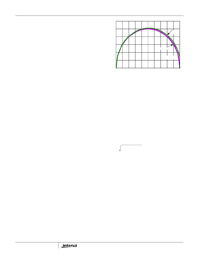
�0.25Io�
�0.5Io�
�Output� Inductor� Selection�
�The� output� inductor� is� selected� to� meet� the� output� voltage�
�ripple� requirements� and� minimize� the� converter� ’s� response�
�0.20�
�0.10�
�Δ� I� =� 0Io�
�time� to� the� load� transient.� The� inductor� value� determines� the�
�converter� ’s� ripple� current� and� the� ripple� voltage� is� a� function�
�0.00�
�0�
�0.1�
�0.2�
�0.3�
�0.4�
�0.5�
�0.6�
�0.7�
�0.8�
�0.9�
�1.0�
�of� the� ripple� current.� The� ripple� voltage� and� current� are�
�approximated� by� Equation� 11:�
�DUTY� CYCLE� (D)�
�FIGURE� 11.� INPUT-CAPACITOR� CURRENT� MULTIPLIER� FOR�
�SINGLE-PHASE� BUCK� CONVERTER�
�V� IN� -� V� OUT� V� OUT�
�Δ� I� =� --------------------------------� ?� ----------------�
�F� S� x� L� V� IN�
�Δ� V� OUT� =� Δ� I� x� ESR�
�(EQ.� 11)�
�capacitors� for� high� frequency� decoupling� and� bulk� capacitors�
�to� supply� the� current� needed� each� time� Q� 1� turns� on.� Place� the�
�Increasing� the� value� of� inductance� reduces� the� ripple� current�
�and� voltage.� However,� the� large� inductance� values� reduce�
�the� converter� ’s� response� time� to� a� load� transient.�
�One� of� the� parameters� limiting� the� converter’s� response� to� a�
�load� transient� is� the� time� required� to� change� the� inductor�
�current.� Given� a� sufficiently� fast� control� loop� design,� the�
�ISL8105� will� provide� either� 0%� or� 100%� duty� cycle� in� response�
�to� a� load� transient.� The� response� time� is� the� time� required� to�
�slew� the� inductor� current� from� an� initial� current� value� to� the�
�transient� current� level.� During� this� interval� the� difference�
�between� the� inductor� current� and� the� transient� current� level�
�must� be� supplied� by� the� output� capacitor.� Minimizing� the�
�small� ceramic� capacitors� physically� close� to� the� MOSFETs�
�and� between� the� drain� of� Q� 1� and� the� source� of� Q� 2� .�
�The� important� parameters� for� the� bulk� input� capacitor� are� the�
�voltage� rating� and� the� RMS� current� rating.� For� reliable�
�operation,� select� the� bulk� capacitor� with� voltage� and� current�
�ratings� above� the� maximum� input� voltage� and� largest� RMS�
�current� required� by� the� circuit.� The� capacitor� voltage� rating�
�should� be� at� least� 1.25x� greater� than� the� maximum� input�
�voltage� and� a� voltage� rating� of� 1.5x� is� a� conservative�
�guideline.� The� RMS� current� rating� requirement� for� the� input�
�capacitor� of� a� buck� regulator� is� approximately� as� shown� in�
�Equation� 13..�
�I� O� (� D� –� D� 2� )� +� --------� D�
�V� O�
�response� time� can� minimize� the� output� capacitance� required.�
�The� response� time� to� a� transient� is� different� for� the�
�application� of� load� and� the� removal� of� load.� Equation� 12�
�I� IN� ,� RMS� =�
�OR�
�2� Δ� I� 2�
�12�
�D� =� ----------�
�VIN�
�(EQ.� 13)�
�gives� the� approximate� response� time� interval� for� application�
�and� removal� of� a� transient� load:�
�I� IN� ,� RMS� =� K� ICM� ?� I� O�
�t� RISE� =� --------------------------------�
�t� FALL� =� -------------------------------�
�L� O� � I� TRAN�
�V� IN� –� V� OUT�
�L� O� � I� TRAN�
�V� OUT�
�(EQ.� 12)�
�For� a� through-hole� design,� several� electrolytic� capacitors�
�(Panasonic� HFQ� series� or� Nichicon� PL� series� or� Sanyo�
�MV-GX� or� equivalent)� may� be� needed.� For� surface� mount�
�where:�
�I� TRAN� is� the� transient� load� current� step�
�t� RISE� is� the� response� time� to� the� application� of� load�
�t� FALL� is� the� response� time� to� the� removal� of� load�
�With� a� lower� input� source� such� as� 1.8V� or� 3.3V,� the� worst�
�case� response� time� can� be� either� at� the� application� or�
�removal� of� load� and� dependent� upon� the� output� voltage�
�setting.� Be� sure� to� check� both� of� these� equations� at� the�
�minimum� and� maximum� output� levels� for� the� worst� case�
�response� time.�
�Input� Capacitor� Selection�
�Use� a� mix� of� input� bypass� capacitors� to� control� the� voltage�
�overshoot� across� the� MOSFETs.� Use� small� ceramic�
�13�
�designs,� solid� tantalum� capacitors� can� be� used,� but� caution�
�must� be� exercised� with� regard� to� the� capacitor� surge� current�
�rating.� These� capacitors� must� be� capable� of� handling� the�
�surge-current� at� power-up.� The� TPS� series,� available� from�
�AVX,� and� the� 593D,� available� series� from� Sprague,� are� both�
�surge� current� tested.�
�MOSFET� Selection/Considerations�
�The� ISL8105� requires� 2� N-Channel� power� MOSFETs.� These�
�should� be� selected� based� upon� r� DS(ON)� ,� gate� supply�
�requirements,� and� thermal� management� requirements.�
�In� high-current� applications,� the� MOSFET� power� dissipation,�
�package� selection� and� heatsink� are� the� dominant� design�
�factors.� The� power� dissipation� includes� two� loss�
�FN6306.5�
�April� 15,� 2010�
�相关PDF资料 |
PDF描述 |
|---|---|
| B41042A7567M | 560UF 35V 12.5X20 SINGLE END |
| AGM06DRMN-S288 | CONN EDGECARD EXTEND 12POS .156 |
| VI-2TP-EY-F4 | CONVERTER MOD DC/DC 13.8V 50W |
| AYM06DRMH-S288 | CONN EDGECARD 12POS .156 EXTEND |
| B41042A6397M | 390UF 50V 12.5X25 SINGLE END |
相关代理商/技术参数 |
参数描述 |
|---|---|
| ISL8105CRZ-T | 功能描述:IC REG CTRLR BUCK PWM VM 10-DFN RoHS:是 类别:集成电路 (IC) >> PMIC - 稳压器 - DC DC 切换控制器 系列:- 标准包装:4,500 系列:PowerWise® PWM 型:控制器 输出数:1 频率 - 最大:1MHz 占空比:95% 电源电压:2.8 V ~ 5.5 V 降压:是 升压:无 回扫:无 反相:无 倍增器:无 除法器:无 Cuk:无 隔离:无 工作温度:-40°C ~ 125°C 封装/外壳:6-WDFN 裸露焊盘 包装:带卷 (TR) 配用:LM1771EVAL-ND - BOARD EVALUATION LM1771 其它名称:LM1771SSDX |
| ISL8105EVAL1 | 制造商:INTERSIL 制造商全称:Intersil Corporation 功能描述:+5V or +12V Single-Phase Synchronous Buck Converter PWM Controller with Integrated MOSFET Gate Drivers |
| ISL8105IBZ | 功能描述:IC REG CTRLR BUCK PWM VM 8-SOIC RoHS:是 类别:集成电路 (IC) >> PMIC - 稳压器 - DC DC 切换控制器 系列:- 产品培训模块:Lead (SnPb) Finish for COTS Obsolescence Mitigation Program 标准包装:2,500 系列:- PWM 型:电流模式 输出数:1 频率 - 最大:275kHz 占空比:50% 电源电压:18 V ~ 110 V 降压:无 升压:无 回扫:无 反相:无 倍增器:无 除法器:无 Cuk:无 隔离:是 工作温度:-40°C ~ 85°C 封装/外壳:8-SOIC(0.154",3.90mm 宽) 包装:带卷 (TR) |
| ISL8105IBZ-T | 功能描述:IC REG CTRLR BUCK PWM VM 8-SOIC RoHS:是 类别:集成电路 (IC) >> PMIC - 稳压器 - DC DC 切换控制器 系列:- 产品培训模块:Lead (SnPb) Finish for COTS Obsolescence Mitigation Program 标准包装:2,500 系列:- PWM 型:电流模式 输出数:1 频率 - 最大:275kHz 占空比:50% 电源电压:18 V ~ 110 V 降压:无 升压:无 回扫:无 反相:无 倍增器:无 除法器:无 Cuk:无 隔离:是 工作温度:-40°C ~ 85°C 封装/外壳:8-SOIC(0.154",3.90mm 宽) 包装:带卷 (TR) |
| ISL8105IRZ | 功能描述:IC REG CTRLR BUCK PWM VM 10-DFN RoHS:是 类别:集成电路 (IC) >> PMIC - 稳压器 - DC DC 切换控制器 系列:- 产品培训模块:Lead (SnPb) Finish for COTS Obsolescence Mitigation Program 标准包装:2,500 系列:- PWM 型:电流模式 输出数:1 频率 - 最大:275kHz 占空比:50% 电源电压:18 V ~ 110 V 降压:无 升压:无 回扫:无 反相:无 倍增器:无 除法器:无 Cuk:无 隔离:是 工作温度:-40°C ~ 85°C 封装/外壳:8-SOIC(0.154",3.90mm 宽) 包装:带卷 (TR) |
发布紧急采购,3分钟左右您将得到回复。