参数资料
| 型号: | ISL84715IH-T |
| 厂商: | Intersil |
| 文件页数: | 4/10页 |
| 文件大小: | 0K |
| 描述: | IC SWITCH SPST SC70-5 |
| 标准包装: | 1 |
| 功能: | 开关 |
| 电路: | 1 x SPST- NO |
| 导通状态电阻: | 400 毫欧 |
| 电压电源: | 单电源 |
| 电压 - 电源,单路/双路(±): | 1.65 V ~ 3.6 V |
| 电流 - 电源: | 18nA |
| 工作温度: | -40°C ~ 85°C |
| 安装类型: | 表面贴装 |
| 封装/外壳: | 6-TSSOP(5 引线),SC-88A,SOT-353 |
| 供应商设备封装: | SC-70-5 |
| 包装: | 剪切带 (CT) |
| 其它名称: | ISL84715IH-CT |
ISL84715, ISL84716
3
FN6087.3
February 23, 2012
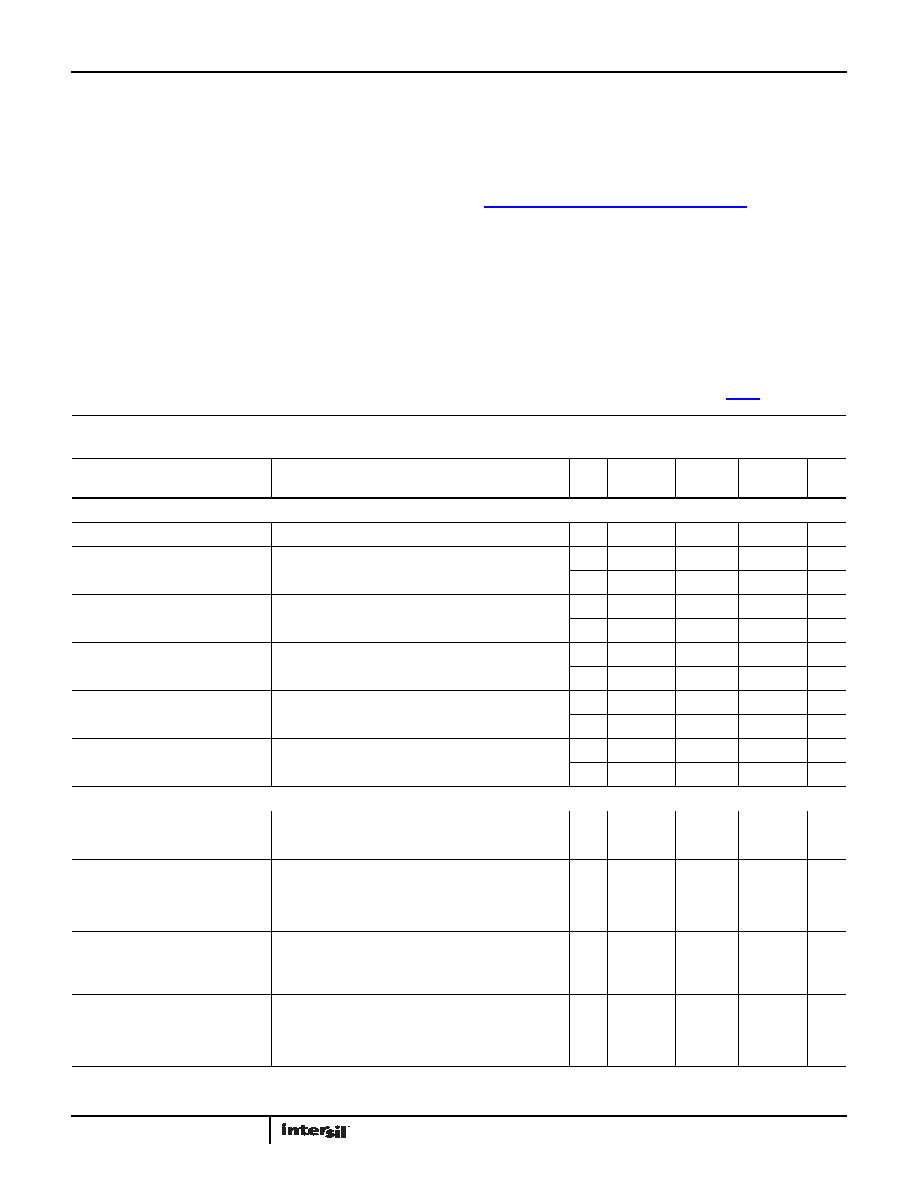
Absolute Maximum Ratings
Thermal Information
V+ to GND . . . . . . . . . . . . . . . . . . . . . . . . . . . . . . . . . . . . . . . . . . . -0.3 to 4.8V
Input Voltages
NO, NC, IN (Note 5) . . . . . . . . . . . . . . . . . . . . . . . . . . . -0.3 to ((V+) + 0.3V)
Output Voltages
COM (Note 5). . . . . . . . . . . . . . . . . . . . . . . . . . . . . . . . -0.3 to ((V+) + 0.3V)
Continuous Current NO, NC, or COM . . . . . . . . . . . . . . . . . . . . . . . . ±300mA
Peak Current NO, NC, or COM
(Pulsed 1ms, 10% Duty Cycle, Max). . . . . . . . . . . . . . . . . . . . . . . ±600mA
ESD Rating:
Human Body Model . . . . . . . . . . . . . . . . . . . . . . . . . . . . . . . . . . . . . . . >4kV
Machine Model . . . . . . . . . . . . . . . . . . . . . . . . . . . . . . . . . . . . . . . . . . >300V
Charged Device Model . . . . . . . . . . . . . . . . . . . . . . . . . . . . . . . . . .>1000V
Thermal Resistance (Typical)
θJA (°C/W)
5 Ld SC70 Package (Note 6). . . . . . . . . . . . . . . . . . . . . .
660
Maximum Junction Temperature (Plastic Package) . . . . . . . . . . . .+150°C
Maximum Storage Temperature Range. . . . . . . . . . . . . . . . . -65°C to +150°C
Pb-Free Reflow Profile . . . . . . . . . . . . . . . . . . . . . . . . . . . . . . . see link below
http://www.intersil.com/pbfree/Pb-FreeReflow.asp
Operating Conditions
Temperature Range
ISL8471XIHZ . . . . . . . . . . . . . . . . . . . . . . . . . . . . . . . . . . . . . -40°C to +85°C
CAUTION: Do not operate at or near the maximum ratings listed for extended periods of time. Exposure to such conditions may adversely impact product
reliability and result in failures not covered by warranty
NOTES:
5. Signals on NC, NO, IN, or COM exceeding V+ or GND are clamped by internal diodes. Limit forward diode current to maximum current ratings.
6.
θJA is measured with the component mounted on a high effective thermal conductivity test board in free air. See Tech Brief TB379 for details.
Electrical Specifications - 3V Supply Test Conditions: V+ = +2.7V to +3.6V, GND = 0V, VINH = 1.4V, VINL = 0.5V (Notes 7, 9),
unless otherwise specified. Boldface limits apply over the operating temperature range, -40°C to +85°C.
PARAMETER
TEST CONDITIONS
TEMP
(°C)
MIN
(Notes 8, 9)
TYP
MAX
(Notes 8, 9) UNITS
ANALOG SWITCH CHARACTERISTICS
Analog Signal Range, VANALOG
Full
0
-
V+
V
ON Resistance, RON
V+ = 2.7V, ICOM = 100mA, VNO or VNC = 1.5V
(See Figure 4)
25
-
0.26
0.4
Full
-
0.45
RON Flatness, RFLAT(ON)
V+ = 2.7V, ICOM = 100mA, VNO or VNC = 0.6V, 1.5V, 2.1V
(Note 10)
25
-
0.038
0.07
Full
-
0.09
NO or NC OFF Leakage Current,
INO(OFF) or INC(OFF)
V+ = 3.3V, VCOM = 0.3V, 3V, VNO or VNC = 3V, 0.3V
25
-3
-
3
nA
Full
-20
-
20
nA
COM OFF Leakage Current, ICOM(OFF) V+ = 3.3V, VCOM = 0.3V, 3V, VNO or VNC = 3V, 0.3V
25
-3
-
3
nA
Full
-20
-
20
nA
COM ON Leakage Current, ICOM(ON)
V
+ = 3.3V, VCOM = 0.3V, 3V, or VNO or VNC = 0.3V, 3V, or
Floating
25
-3
-
3
nA
Full
-35
-
35
nA
DYNAMIC CHARACTERISTICS
Turn-ON Time, tON
V+ = 2.7V, VNO or VNC = 1.5V, RL = 50, CL = 35pF
(See Figure 1)
25
-
9
12
ns
Full
-
15
ns
Turn-OFF Time, tOFF
V+ = 2.7V, VNO or VNC = 1.5V, RL = 50, CL = 35pF
(See Figure 1)
25
-
5
8
ns
Full
-
11
ns
Charge Injection, Q
25
-
70
-
pC
OFF Isolation
RL = 50, CL = 5pF, f = 1MHz, VCOM = 1VRMS
(See Figure 3)
25
-
-45
-
dB
Total Harmonic Distortion
f = 20Hz to 20kHz, VCOM = 2VP-P, RL = 32
25
-
0.003
-
%
NO or NC OFF Capacitance, COFF
25
-
68
-
pF
COM OFF Capacitance, CCOM(OFF)
25
-
68
-
pF
COM ON Capacitance, CCOM(ON)
25
-
160
-
pF
相关PDF资料 |
PDF描述 |
|---|---|
| ISL84762IU-T | IC SWITCH DUAL SPDT 10MSOP |
| ISL84780IV-T | IC SWITCH QUAD SPDT 16TSSOP |
| ISL84781IV-T | IC MUX/DEMUX 8X1 16TSSOP |
| ISL84782IV-T | IC MUX/DEMUX DUAL 4X1 16TSSOP |
| ISL8484IU-T | IC SWITCH DUAL SPDT 10MSOP |
相关代理商/技术参数 |
参数描述 |
|---|---|
| ISL84715IHZ-T | 功能描述:IC SWITCH SPST SC70-5 RoHS:是 类别:集成电路 (IC) >> 接口 - 模拟开关,多路复用器,多路分解器 系列:- 标准包装:2,500 系列:- 功能:视频交叉点开关 电路:1 x 8:6 导通状态电阻:- 电压电源:单电源 电压 - 电源,单路/双路(±):3.135 V ~ 5.25 V 电流 - 电源:55mA 工作温度:-40°C ~ 85°C 安装类型:表面贴装 封装/外壳:24-TSSOP(0.173",4.40mm 宽) 供应商设备封装:24-TSSOP 包装:带卷 (TR) 产品目录页面:1214 (CN2011-ZH PDF) 其它名称:FMS6502MTC24XTR |
| ISL84716 | 制造商:INTERSIL 制造商全称:Intersil Corporation 功能描述:Ultra Low ON-Resistance, Low Voltage, Single Supply, SPST Analog Switches |
| ISL84716IH-T | 功能描述:模拟开关 IC SPST NC RoHS:否 制造商:Texas Instruments 开关数量:2 开关配置:SPDT 开启电阻(最大值):0.1 Ohms 切换电压(最大): 开启时间(最大值): 关闭时间(最大值): 工作电源电压:2.7 V to 4.5 V 最大工作温度:+ 85 C 安装风格:SMD/SMT 封装 / 箱体:DSBGA-16 |
| ISL84716IHZ-T | 功能描述:IC SWITCH SPST SC70-5 RoHS:是 类别:集成电路 (IC) >> 接口 - 模拟开关,多路复用器,多路分解器 系列:- 标准包装:1 系列:- 功能:开关 电路:2 x SPST - NC/NO 导通状态电阻:8 欧姆 电压电源:单电源 电压 - 电源,单路/双路(±):2.3 V ~ 4.3 V 电流 - 电源:1µA 工作温度:-40°C ~ 85°C 安装类型:表面贴装 封装/外壳:8-UFQFN 供应商设备封装:8-迷你型QFN(1.4x1.4) 包装:剪切带 (CT) 其它名称:DG2738DN-T1-E4CT |
| ISL84762 | 制造商:INTERSIL 制造商全称:Intersil Corporation 功能描述:Ultra Low ON-Resistance, Low Voltage, Single Supply, Dual SPDT Analog Switch |
发布紧急采购,3分钟左右您将得到回复。