参数资料
| 型号: | ISL95870BHRZ |
| 厂商: | Intersil |
| 文件页数: | 18/28页 |
| 文件大小: | 0K |
| 描述: | IC CTRLR PWM 1PHASE GPU 20QFN |
| 标准包装: | 75 |
| 应用: | 控制器,GPU 内核电源 |
| 输入电压: | 3.3 V ~ 25 V |
| 输出数: | 1 |
| 输出电压: | 0.5 V ~ 5 V |
| 工作温度: | -10°C ~ 100°C |
| 安装类型: | 表面贴装 |
| 封装/外壳: | 20-VFQFN 裸露焊盘 |
| 供应商设备封装: | 20-QFN(3x4) |
| 包装: | 管件 |
第1页第2页第3页第4页第5页第6页第7页第8页第9页第10页第11页第12页第13页第14页第15页第16页第17页当前第18页第19页第20页第21页第22页第23页第24页第25页第26页第27页第28页
�� �
�
�ISL95870,� ISL95870A,� ISL95870B�
�The� ISL95870B� V� SET3� setpoint� is� written� as� Equation� 23:�
�V� SET3� =� V� REF� ?� ?� 1� +� --------------------------------------------� ?�
�?� R� SET1� +� R� SET2� ?�
�?� R� SET3� +� R� SET4� ?�
�(EQ.� 23)�
�VOUT�
�RFB�
�FB�
�-�
�VCOMP�
�The� ISL95870B� V� SET4� setpoint� is� written� as� Equation� 24:�
�+�
�EA�
�V� SET4� =� V� REF� ?� ?� 1� +� ---------------------------------------------------------------------� ?�
�?� R� SET1� +� R� SET2� +� R� SET3� ?�
�?� R� SET4� ?�
�(EQ.� 24)�
�+�
�VREF�
�0.5V�
�V� SET�
�The� V� SET1� is� fixed� at� 0.5V� because� it� corresponds� to� the� closure�
�of� internal� switch� SW0� that� configures� the� V� SET� amplifier� as� a�
�unity-gain� voltage� follower� for� the� 0.5V� voltage� reference� V� REF� .�
�The� setpoint� reference� voltages� use� the� naming� convention�
�V� SET(x)� where� (x)� is� the� first,� second,� third,� or� fourth� setpoint�
�reference� voltage� where:�
�-� V� SET1� <� V� SET2� <� V� SET3� <� V� SET4� thus,�
�SREF�
�SET0�
�SW0�
�SW1�
�-�
�-� V� OUT1� <� V� OUT2� <� V� OUT3� <� V� OUT4�
�V� REF� ?� V� SET2�
�For� given� four� user� selected� reference� voltages� V� SETx� ,� the�
�programmed� resistors� R� SET1� ,� R� SET2� ,� R� SET3� and� R� SET4� are�
�designed� in� the� following� way.� First,� assign� an� initial� value� to� R� SET4�
�of� approximately� 100k� Ω� then� calculate� R� SET1,� R� SET2� and� R� SET3�
�using� Equations� 25,� 26,� and� 27� respectively.�
�R� SET4� ?� V� SET4� ?� (� V� SET2� –� V� REF� )�
�(EQ.� 25)�
�R� SET1� =� -------------------------------------------------------------------------------------------�
�SET1�
�SET2�
�SW2�
�SW3�
�V� SET2� ?� V� SET3�
�R� SET4� ?� V� SET4� ?� (� V� SET3� –� V� SET2� )�
�R� SET2� =� ----------------------------------------------------------------------------------------------�
�(EQ.� 26)�
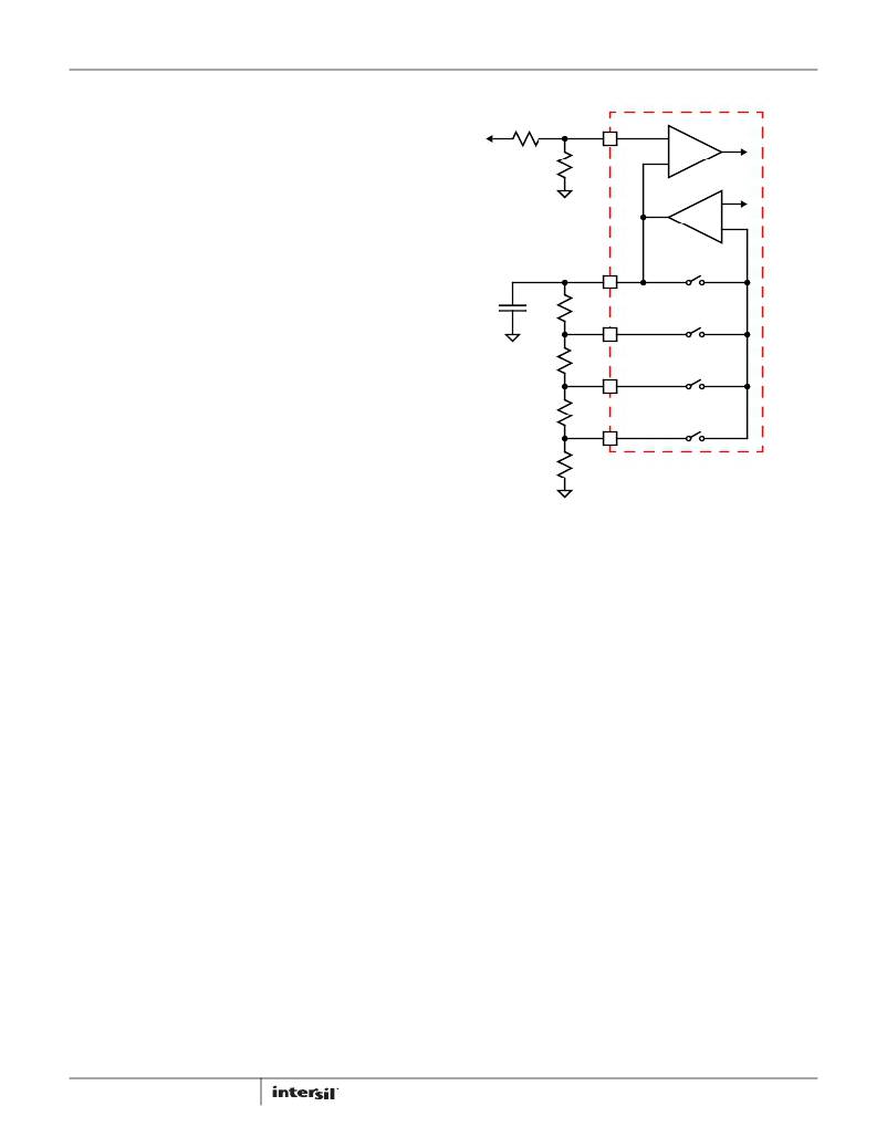
�FIGURE� 11.� ISL95870B� VOLTAGE� PROGRAMMING� CIRCUIT�
�R� SET4� ?� (� V� SET4� –� V� SET3� )�
�R� SET3� =� -----------------------------------------------------------------------�
�R� SET1� +� R� SET2� +� R� SET3� +� R� SET4� ?� 300k� Ω�
�R� FB� +� R� OFS�
�V� OUT� =� V� SREF� ?� ----------------------------------� =� V� SREF� ?� k�
�R�
�V� OUTx� =� V� SETx� ?� k�
�(EQ.� 27)�
�V� SET3�
�The� sum� of� all� the� programming� resistors� should� be�
�approximately� 300k� Ω,� as� shown� in� Equation� 28,� otherwise�
�adjust� the� value� of� R� SET4� and� repeat� the� calculations.�
�(EQ.� 28)�
�If� the� output� voltage� is� in� the� range� of� 0.5V� to� 1.5V,� the� external�
�resistor-divider� is� not� necessary.� The� output� voltage� is� equal� to�
�one� of� the� reference� voltages� depending� on� the� status� of� VID1�
�and� VID0.� The� external� resistor� divider� consisting� of� R� FB� and�
�R� OFS� allows� the� user� to� program� the� output� voltage� in� the� range�
�of� 1.5V� to� 5V.� The� relation� between� the� output� voltage� and� the�
�reference� is� given� in� Equation� 29:�
�(EQ.� 29)�
�OFS�
�In� this� case,� the� four� output� voltages� are� equal� to� each� of� the�
�corresponding� reference� voltages� multiplying� the� factor� k.�
�(EQ.� 30)�
�18�
�High� Output� Voltage� Programming�
�The� ISL95870� has� a� fixed� 0.5V� reference� voltage� (V� SREF� ).� For�
�high� output� voltage� application,� the� resistor� divider� consisting� of�
�R� FB� and� R� OFS� requires� large� ratio� (R� FB� :R� OFS� =� 9:1� for� 5V�
�output).� The� FB� pin� with� large� ratio� resistor� divider� is� noise�
�sensitive� and� the� PCB� layout� should� be� carefully� routed.� It� is�
�recommended� to� use� small� value� resistor� divider� such� as�
�R� FB� =1k� Ω.�
�In� general� the� ISL95870A� and� ISL95870B� have� much� better�
�jitter� performance� than� the� ISL95870� when� the� output� voltage� is�
�in� the� range� of� 3.3V� to� 5V,� particularly� in� DCM.� This� is� because�
�V� SREF� voltage� can� be� set� to� 1.5V� and� a� smaller� ratio� resistor�
�divider� can� be� used.� This� makes� the� singal� to� noise� ratio� at� FB� pin�
�much� better.� So� for� 3.3V� to� 5V� output,� the� ISL95870A� and�
�ISL95870B� are� recommended� with� V� SREF� set� to� 1.5V.�
�R4� Modulator�
�The� R� 4� modulator� is� an� evolutionary� step� in� R� 3� technology.� Like�
�R� 3� ,� the� R� 4� modulator� allows� variable� frequency� in� response� to�
�load� transients� and� maintains� the� benefits� of� current-mode�
�hysteretic� controllers.� However,� in� addition,� the� R� 4� modulator�
�reduces� regulator� output� impedance� and� uses� accurate�
�referencing� to� eliminate� the� need� for� a� high-gain� voltage�
�amplifier� in� the� compensation� loop.� The� result� is� a� topology� that�
�can� be� tuned� to� voltage-mode� hysteretic� transient� speed� while�
�maintaining� a� linear� control� model� and� removes� the� need� for� any�
�compensation.� This� greatly� simplifies� the� regulator� design� for�
�customers� and� reduces� external� component� cost.�
�FN6899.1�
�December� 2,� 2013�
�相关PDF资料 |
PDF描述 |
|---|---|
| MIC5320-NNYMT TR | IC REG LDO 2.85V .15A 6-TMLF |
| MIC37501-2.5WR | IC REG LDO 2.5V SPAK-7 |
| FMM08DSEI | CONN EDGECARD 16POS .156 EYELET |
| 200MXG820MEFCSN22X45 | CAP ALUM 820UF 200V 20% SNAP-IN |
| LT3060MPTS8#TRMPBF | IC REG LDO ADJ .1A 8TSOT |
相关代理商/技术参数 |
参数描述 |
|---|---|
| ISL95870BHRZ-T | 功能描述:电流型 PWM 控制器 0/2 BIT PWM GPU CONTLR FOR NOTEBOOK RoHS:否 制造商:Texas Instruments 开关频率:27 KHz 上升时间: 下降时间: 工作电源电压:6 V to 15 V 工作电源电流:1.5 mA 输出端数量:1 最大工作温度:+ 105 C 安装风格:SMD/SMT 封装 / 箱体:TSSOP-14 |
| ISL95870BHRZ-TS2490 | 制造商:Intersil Corporation 功能描述:IBM, ISL95870BHRZ-T W/CONTAINER LABELING - Tape and Reel |
| ISL95870BHRZ-TS2568 | 制造商:Intersil Corporation 功能描述:INTEL, ISL95870BHRTZ-T W/BARCODE LABELS, 12 MONTH D/C RESTRI - Tape and Reel |
| ISL95870BIRZ | 功能描述:电流型 PWM 控制器 0/2 BIT PWM GPU CONTLR FOR NOTEBOOK RoHS:否 制造商:Texas Instruments 开关频率:27 KHz 上升时间: 下降时间: 工作电源电压:6 V to 15 V 工作电源电流:1.5 mA 输出端数量:1 最大工作温度:+ 105 C 安装风格:SMD/SMT 封装 / 箱体:TSSOP-14 |
| ISL95870BIRZ-T | 功能描述:电流型 PWM 控制器 0/2 BIT PWM GPU CONTLR FOR NOTEBOOK RoHS:否 制造商:Texas Instruments 开关频率:27 KHz 上升时间: 下降时间: 工作电源电压:6 V to 15 V 工作电源电流:1.5 mA 输出端数量:1 最大工作温度:+ 105 C 安装风格:SMD/SMT 封装 / 箱体:TSSOP-14 |
发布紧急采购,3分钟左右您将得到回复。