参数资料
| 型号: | ISL97656IRTZ |
| 厂商: | Intersil |
| 文件页数: | 6/9页 |
| 文件大小: | 0K |
| 描述: | IC REG BOOST ADJ 4A 10TDFN |
| 标准包装: | 100 |
| 类型: | 升压(升压) |
| 输出类型: | 可调式 |
| 输出数: | 1 |
| 输出电压: | 5 V ~ 25 V |
| 输入电压: | 2.3 V ~ 6 V |
| PWM 型: | 电流模式 |
| 频率 - 开关: | 640kHz,1.2MHz |
| 电流 - 输出: | 4A |
| 同步整流器: | 无 |
| 工作温度: | -40°C ~ 85°C |
| 安装类型: | 表面贴装 |
| 封装/外壳: | 10-WFDFN 裸露焊盘 |
| 包装: | 管件 |
| 供应商设备封装: | 10-TDFN-EP(3x3) |
�� �
�
�ISL97656�
�Applications� Information�
�.�
�L�
�D�
�The� ISL97656� is� a� high� frequency,� high� efficiency� boost� regulator�
�operated� at� constant� frequency� PWM� mode.� The� boost� converter�
�V� IN�
�C� IN�
�C� OUT�
�V� OUT�
�stores� energy� from� an� input� voltage� source� and� delivers� higher�
�output� voltage.� The� input� voltage� range� is� 2.2V� to� 6.0V� and� the�
�output� voltage� range� is� 5V� to� 25V.� The� switching� frequency� can� be�
�selected� between� 640kHz� and� 1.22MHz.� The� higher� switching�
�frequency� allows� use� of� smaller� inductors� and� faster� transient�
�response.� An� external� compensation� pin� gives� the� user� greater�
�ISL97656�
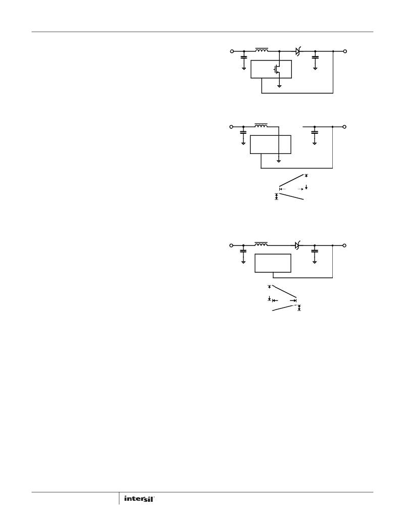
�FIGURE� 13.� BOOST� CONVERTER�
�flexibility� in� setting� output� transient� response� and� tighter� load�
�regulation.� The� converter� soft-start� characteristic� can� be�
�controlled� by� the� external� C� SS� capacitor.� The� EN� pin� allows� the�
�user� to� shut� down� the� device.�
�V� IN�
�C� IN�
�L�
�C� OUT�
�V� OUT�
�Boost� Converter� Operations�
�Figure� 13� shows� a� boost� converter� with� all� the� key� components.�
�In� steady� state� and� continuous� conduction� mode,� the� boost�
�ISL97656�
�converter� operates� in� two� cycles.� During� the� first� cycle,� as� shown�
�in� Figure� 14,� the� internal� power� FET� turns� on� and� the� Schottky�
�I� L�
�Δ� I� L1�
�diode� is� reverse� biased� and� cuts� off� the� current� flow� to� the�
�output.� The� output� current� is� supplied� from� the� output� capacitor.�
�The� voltage� across� the� inductor� is� V� IN� and� the� inductor� current�
�ramps� up� with� a� rate� of� V� IN� /L,� where� L� is� the� inductance.� The�
�inductor� is� magnetized� and� energy� is� stored� in� the� inductor.� The�
�change� in� inductor� current� is� shown� in� Equation� 1:�
�Δ� T� 1�
�Δ� V� O�
�FIGURE� 14.� BOOST� CONVERTER� -� CYCLE� 1,� POWER� SWITCH� CLOSED�
�Δ� I� L1� =� Δ� T1� ×� ---------�
�Δ� T1� =� ----------�
�D�
�f� SW�
�V� IN�
�L�
�V� IN�
�C� IN�
�L�
�D�
�C� OUT�
�V� OUT�
�D� =� Duty� Cycle�
�ISL97656�
�Δ� V� O� =� ----------------� ×� Δ� T� 1�
�C� OUT�
�I� OUT�
�(EQ.� 1)�
�During� the� second� cycle,� the� power� FET� turns� off� and� the�
�Schottky� diode� is� forward� biased,� (see� Figure� 15).� The� energy�
�stored� in� the� inductor� is� supplied� to� the� output.� This� energy� is�
�Δ� I� L2�
�Δ� T� 2�
�I� L�
�Δ� V� O�
�Δ� I� L� =� Δ� T2� ×� --------------------------------�
�used� to� charge� the� output� capacitor� and� supply� output� current.� In�
�this� cycle� switching� node� (LX)� is� held� to� V� OUT� +� Schottky� diode�
�drop.� Voltage� drop� across� the� inductor� is� V� IN� -� V� OUT� (ignoring�
�diode� drop� across� Schottky� diode).� The� change� in� inductor�
�current� during� the� second� cycle� is� shown� in� Equation� 2:�
�V� IN� –� V� OUT�
�L�
�FIGURE� 15.� BOOST� CONVERTER� -� CYCLE� 2,� POWER� SWITCH� OPEN�
�Output� Voltage�
�An� external� feedback� resistor� divider� is� required� to� divide� the�
�output� voltage� down� to� the� nominal� 1.24V� reference� voltage.� The�
�current� drawn� by� the� resistor� network� should� be� limited� to�
�Δ� T2� =� -------------�
�1� –� D�
�f� SW�
�(EQ.� 2)�
�maintain� the� overall� converter� efficiency.� The� maximum� value� of�
�the� resistor� network� is� limited� by� the� feedback� input� bias� current�
�and� the� potential� for� noise� being� coupled� into� the� feedback� pin.� A�
�In� steady� state� operation,� the� change� in� the� inductor� current�
�must� be� equal� as� shown� in� Equation� 3.�
�Δ� I1� +� Δ� I2� =� 0�
�resistor� network� less� than� 100k� is� recommended.� The� boost�
�converter� output� voltage� is� determined� by� the� relationship� as�
�shown� in� Equation� 4.� The� nominal� VFB� voltage� is� 1.24V.�
�D� V� IN� 1� –� D� V� IN� –� V� OUT�
�f� SW�
�f� SW�
�V� OUT� =� V� FB� � ?� 1� +� -------� ?�
�----------� � ---------� +� -------------� � --------------------------------� =� 0�
�L� L�
�?� R� 1� ?�
�?� R� 2� ?�
�(EQ.� 4)�
�V� OUT� 1�
�V� IN�
�----------------� =� -------------�
�1� –� D�
�6�
�(EQ.� 3)�
�FN6439.6�
�July� 19,� 2012�
�相关PDF资料 |
PDF描述 |
|---|---|
| ISL97701IRZ | IC REG BOOST ADJ 0.1A 10DFN |
| ISL97702IRZ-T7 | IC REG BOOST ADJ 0.13A DL 10DFN |
| ISL98012IUZ | IC REG BOOST ADJ 0.6A 10MSOP |
| ISPPAC-POWR1208-01TN44E | IC ISP POWER MGR ANLG/LOG 44TQFP |
| ISPPAC-POWR604-01TN44E | IC ISP POWER MGR ANLG/LOG 44TQFP |
相关代理商/技术参数 |
参数描述 |
|---|---|
| ISL97656IRTZEVALZ | 功能描述:EVAL BOARD FOR ISL97656IRTZ RoHS:是 类别:编程器,开发系统 >> 评估板 - DC/DC 与 AC/DC(离线)SMPS 系列:* 产品培训模块:Obsolescence Mitigation Program 标准包装:1 系列:True Shutdown™ 主要目的:DC/DC,步升 输出及类型:1,非隔离 功率 - 输出:- 输出电压:- 电流 - 输出:1A 输入电压:2.5 V ~ 5.5 V 稳压器拓扑结构:升压 频率 - 开关:3MHz 板类型:完全填充 已供物品:板 已用 IC / 零件:MAX8969 |
| ISL97656IRTZ-T | 功能描述:IC REG BOOST ADJ 4A 10TDFN RoHS:是 类别:集成电路 (IC) >> PMIC - 稳压器 - DC DC 开关稳压器 系列:- 产品培训模块:Lead (SnPb) Finish for COTS Obsolescence Mitigation Program 标准包装:2,500 系列:- 类型:降压(降压) 输出类型:两者兼有 输出数:1 输出电压:5V,1 V ~ 10 V 输入电压:3.5 V ~ 28 V PWM 型:电流模式 频率 - 开关:220kHz ~ 1MHz 电流 - 输出:600mA 同步整流器:无 工作温度:-40°C ~ 125°C 安装类型:表面贴装 封装/外壳:16-SSOP(0.154",3.90mm 宽) 包装:带卷 (TR) 供应商设备封装:16-QSOP |
| ISL97656IRTZ-TK | 功能描述:IC REG BOOST ADJ 4A 10TDFN RoHS:是 类别:集成电路 (IC) >> PMIC - 稳压器 - DC DC 开关稳压器 系列:- 标准包装:1 系列:EZBuck™ 类型:降压(降压) 输出类型:可调式 输出数:1 输出电压:0.8 V ~ 22.1 V 输入电压:3 V ~ 26 V PWM 型:电流模式 频率 - 开关:1.5MHz 电流 - 输出:1.8A 同步整流器:无 工作温度:-40°C ~ 85°C 安装类型:表面贴装 封装/外壳:8-WFDFN 裸露焊盘 包装:剪切带 (CT) 供应商设备封装:8-DFN(2x2) 其它名称:785-1276-1 |
| ISL97656IRTZ-TS2720 | 制造商:Intersil Corporation 功能描述:QUALCOMM, ISL97656IRTZ-T W/BUSINESS TRACKING REQUIREMENTS - Tape and Reel |
| ISL97670 | 制造商:Intersil Corporation 功能描述: |
发布紧急采购,3分钟左右您将得到回复。