- 您现在的位置:买卖IC网 > PDF目录20781 > ISL97686IRTZ-T (Intersil)IC LED DRVR BACKLIGHT 28TQFN PDF资料下载
参数资料
| 型号: | ISL97686IRTZ-T |
| 厂商: | Intersil |
| 文件页数: | 17/23页 |
| 文件大小: | 0K |
| 描述: | IC LED DRVR BACKLIGHT 28TQFN |
| 标准包装: | 6,000 |
| 拓扑: | 线性(LDO),PWM,升压(升压) |
| 输出数: | 4 |
| 内部驱动器: | 是 |
| 类型 - 主要: | 汽车,背光,通用型 |
| 频率: | 200kHz ~ 1.2MHz |
| 电源电压: | 9 V ~ 32 V |
| 输出电压: | 75V |
| 安装类型: | 表面贴装 |
| 封装/外壳: | 28-WFQFN 裸露焊盘 |
| 供应商设备封装: | 28-TQFN-EP(5x5) |
| 包装: | 带卷 (TR) |
| 工作温度: | -40°C ~ 105°C |
�� �
�
�ISL97686�
�PCB� Layout� Considerations�
�Two� Layers� PCB� Layout� with� TQFN� Package�
�Great� care� is� needed� in� designing� a� PC� board� for� stable� ISL97686�
�operation.� As� shown� in� the� typical� application� diagram� (Figure� 1,�
�page� 1),� the� separation� of� PGND� and� AGND� of� each� ISL97686� is�
�essential,� keeping� the� AGND� referenced� only� local� to� the� chip.�
�This� minimizes� switching� noise� injection� to� the� feedback� sensing�
�and� analog� areas,� as� well� as� eliminating� DC� errors� form� high�
�current� flow� in� resistive� PC� board� traces.� PGND� and� AGND� should�
�be� on� the� top� and� bottom� layers� respectively� in� the� two� layer� PCB.�
�A� star� ground� connection� should� be� formed� by� connecting� the�
�LED� ground� return� and� AGND� pins� to� the� thermal� pad� with� 9-12�
�vias.� The� ground� connection� should� be� into� this� ground� net,� on�
�the� top� plane.� The� bottom� plane� then� forms� a� quiet� analog�
�ground� area,� that� both� shields� components� on� the� top� plane,� as�
�well� as� providing� easy� access� to� all� sensitive� components.� For�
�example,� the� ground� side� of� the� ISET1/2� resistors� can� be�
�dropped� to� the� bottom� plane,� providing� a� very� low� impedance�
�path� back� to� the� AGND� pin,� which� does� not� have� any� circulating�
�high� currents� to� interfere� with� it.� The� bottom� plane� can� also� be�
�used� as� a� thermal� ground,� so� the� AGND� area� should� be� sized�
�sufficiently� large� to� dissipate� the� required� power.� For� multi-layer�
�boards,� the� AGND� plane� can� be� the� second� layer.� This� provides�
�easy� access� to� the� AGND� net,� but� allows� a� larger� thermal� ground�
�and� main� ground� supply� to� come� up� through� the� thermal� vias�
�from� a� lower� plane.�
�This� type� of� layout� is� particularly� important� for� this� type� of�
�product,� as� the� ISL97686� has� a� high� power� boost,� resulting� in�
�high� current� flow� in� the� main� loop’s� traces.� Careful� attention�
�should� be� focussed� on� the� below� layout� details:�
�1.� Boost� input� capacitors,� output� capacitors,� inductor� and�
�Schottky� diode� should� be� placed� together� in� a� nice� tight�
�layout.� Keeping� the� grounds� of� the� input,� output,� ISL97686�
�and� the� current� sense� resistor� connected� with� a� low�
�impedance� and� wide� metal� is� very� important� to� keep� these�
�nodes� closely� coupled.�
�2.� Figure� page� 18� shows� important� traces� of� current� sensor� (RS)�
�and� OVP� resistors� (RU,� RL).� The� current� sensor� track� line�
�should� be� short,� so� that� it� remains� as� close� as� possible� to� the�
�Current� Sense� (CS)� pin.� Additionally,� the� CS� pin� is� referenced�
�from� the� adjacent� PGND� pin.� It� is� extremely� important� that�
�this� PGND� pin� is� placed� with� a� good� reference� to� the� bottom�
�of� the� sense� resistor.� In� Figure� 22� you� can� see� that� this� ground�
�pin� is� not� connected� to� the� thermal� pad,� but� instead� used� to�
�effectively� sense� the� voltage� at� the� bottom� of� the� current�
�sense� resistor.� However,� this� pin� also� takes� the� gate� driver�
�current,� so� it� must� still� have� a� wide� connection� and� a� good�
�connection� back� from� the� sense� resistor� to� the� star� ground.�
�Also,� the� RC� filter� on� CS� should� be� placed� referenced� to� this�
�PGND� pin� and� be� close� to� the� chip.�
�3.� If� possible,� try� to� maintain� central� ground� node� on� the� board�
�and� use� the� input� capacitors� to� avoid� excessive� input� ripple� for�
�high� output� current� supplies.� The� filtering� capacitors� should�
�be� placed� close� by� the� VIN� pin.�
�4.� For� optimum� load� regulation� and� true� V� OUT� sensing,� the� OVP�
�resistors� should� be� connected� independently� to� the� top� of� the�
�output� capacitors� and� away� from� the� higher� dv/dt� traces.� The�
�17�
�OVP� connection� then� needs� to� be� as� short� as� possible� to� the�
�pin.� The� AGND� connection� of� the� lower� OVP� components� is�
�critical� for� good� regulation.� At� 70V� output,� a� 100mV� change�
�at� V� OUT� translates� to� a� 1.7mV� change� at� OVP,� so� a� small�
�ground� error� due� to� high� current� flow,� if� referenced� to� PGND,�
�can� be� disastrous.�
�5.� The� bypass� capacitors� connected� to� VDC� and� VLOGIC� need� to�
�be� as� close� to� the� pin� as� possible,� and� again� should� be�
�referenced� to� AGND.� This� is� also� true� for� the� COMP� network� and�
�the� rest� of� the� analog� components� (on� ISEDT1/2,� FPWM,� etc.).�
�6.� The� heat� of� the� chip� is� mainly� dissipated� through� the� exposed�
�thermal� pad� so� maximizing� the� copper� area� around� it� is� a�
�good� idea.� A� solid� ground� is� always� helpful� for� the� thermal�
�and� EMI� performance.�
�7.� The� inductor� and� input� and� output� capacitors� should� be�
�mounted� as� tight� as� possible,� to� reduce� the� audible� noise� and�
�inductive� ringing.�
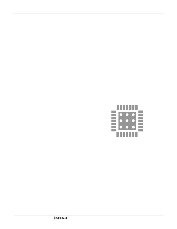
�General� Power� PAD� Design� Considerations�
�Figure� 22� shows� an� example� of� how� to� use� vias� to� remove� heat�
�from� the� IC.� We� recommend� you� fill� the� thermal� pad� area� with�
�vias.� A� typical� via� array� would� be� to� fill� the� thermal� pad� foot� print�
�with� vias� spaced� such� that� the� centre� to� centre� spacing� is� three�
�times� the� radius� of� the� via.� Keep� the� vias� small,� but� not� so� small�
�that� their� inside� diameter� prevents� solder� wicking� through� the�
�holes� during� reflow.�
�FIGURE� 22.� ISL97686� TQFN� PCB� VIA� PATTERN�
�One� Layer� PCB� Layout� with� SOIC� Package�
�The� general� rules� of� two� layer� PCB� layout� can� be� applied� to� the�
�one� layer� PCB� layout� of� the� SOIC� package,� although� this� layout� is�
�much� more� challenging� and� very� easy� to� get� wrong.� The� noisy�
�PGND� of� the� switching� FET� area� and� quiet� AGND� must� be� placed�
�on� the� same� plane� as� shown� in� Figure� 24,� therefore,� great� care�
�must� be� taken� to� maintain� stable� and� clean� operation,� due� to�
�increased� risk� of� noise� injection� to� the� quiet� area.�
�1.� The� GND� plane� should� be� extended� as� far� as� possible� as�
�space� allows� to� spread� out� heat� dissipation.�
�2.� All� ground� pads� for� input� caps,� current� sensor,� output� caps�
�should� be� close� to� the� PGND� pin� adjacent� to� the� CS� pin� of�
�ISL97686� with� wide� metal� connection� shown� in� Figure� 23.�
�This� guarantees� a� low� differential� voltage� between� these�
�critical� points.�
�3.� The� connection� point� between� AGND� pin� 14� and� PGND� pin� 18�
�should� be� “� Narrow”� neck,� effectively� making� a� star� ground� at�
�the� AGND� pin.�
�FN7953.0�
�April� 23,� 2012�
�相关PDF资料 |
PDF描述 |
|---|---|
| MAX6964AEG+ | IC LED DRIVER LINEAR 24-QSOP |
| MAX6968APE+ | IC LED DRIVER LINEAR 16-DIP |
| MAX6971ANG+ | IC LED DRIVER LINEAR 24-DIP |
| ECC08DRES | CONN EDGECARD 16POS .100 EYELET |
| MAX16832CASA+ | IC LED DRIVER HIGH BRIGHT 8-SOIC |
相关代理商/技术参数 |
参数描述 |
|---|---|
| ISL97687IBZ | 功能描述:IC LED DRVR 4 CHAN PWM 28SOIC RoHS:是 类别:集成电路 (IC) >> PMIC - LED 驱动器 系列:- 产品培训模块:Lead (SnPb) Finish for COTS Obsolescence Mitigation Program 标准包装:2,500 系列:- 恒定电流:- 恒定电压:- 拓扑:升压(升压),切换式电容器(充电泵) 输出数:1 内部驱动器:是 类型 - 主要:背光 类型 - 次要:白色 LED 频率:625kHz ~ 875kHz 电源电压:2.7 V ~ 5.3 V 输出电压:5V 安装类型:表面贴装 封装/外壳:10-TFSOP,10-MSOP(0.118",3.00mm 宽) 供应商设备封装:10-µMAX 包装:带卷 (TR) 工作温度:-40°C ~ 85°C |
| ISL97687IBZEV1Z | 制造商:Intersil 功能描述:ISL97687 EVAL |
| ISL97687IBZ-T | 功能描述:IC LED DRVR 4 CHAN PWM 28SOIC RoHS:是 类别:集成电路 (IC) >> PMIC - LED 驱动器 系列:- 产品培训模块:Lead (SnPb) Finish for COTS Obsolescence Mitigation Program 标准包装:2,500 系列:- 恒定电流:- 恒定电压:- 拓扑:升压(升压),切换式电容器(充电泵) 输出数:1 内部驱动器:是 类型 - 主要:背光 类型 - 次要:白色 LED 频率:625kHz ~ 875kHz 电源电压:2.7 V ~ 5.3 V 输出电压:5V 安装类型:表面贴装 封装/外壳:10-TFSOP,10-MSOP(0.118",3.00mm 宽) 供应商设备封装:10-µMAX 包装:带卷 (TR) 工作温度:-40°C ~ 85°C |
| ISL97687IRTZ | 功能描述:IC LED DRVR 4 CHAN PWM 28TQFN RoHS:是 类别:集成电路 (IC) >> PMIC - LED 驱动器 系列:- 产品培训模块:Lead (SnPb) Finish for COTS Obsolescence Mitigation Program 标准包装:2,500 系列:- 恒定电流:- 恒定电压:- 拓扑:升压(升压),切换式电容器(充电泵) 输出数:1 内部驱动器:是 类型 - 主要:背光 类型 - 次要:白色 LED 频率:625kHz ~ 875kHz 电源电压:2.7 V ~ 5.3 V 输出电压:5V 安装类型:表面贴装 封装/外壳:10-TFSOP,10-MSOP(0.118",3.00mm 宽) 供应商设备封装:10-µMAX 包装:带卷 (TR) 工作温度:-40°C ~ 85°C |
| ISL97687IRTZ-T | 功能描述:IC LED DRVR 4 CHAN PWM 28TQFN RoHS:是 类别:集成电路 (IC) >> PMIC - LED 驱动器 系列:- 产品培训模块:Lead (SnPb) Finish for COTS Obsolescence Mitigation Program 标准包装:2,500 系列:- 恒定电流:- 恒定电压:- 拓扑:升压(升压),切换式电容器(充电泵) 输出数:1 内部驱动器:是 类型 - 主要:背光 类型 - 次要:白色 LED 频率:625kHz ~ 875kHz 电源电压:2.7 V ~ 5.3 V 输出电压:5V 安装类型:表面贴装 封装/外壳:10-TFSOP,10-MSOP(0.118",3.00mm 宽) 供应商设备封装:10-µMAX 包装:带卷 (TR) 工作温度:-40°C ~ 85°C |
发布紧急采购,3分钟左右您将得到回复。