- 您现在的位置:买卖IC网 > PDF目录382046 > JAN1N5641 (MICROSEMI CORP-SCOTTSDALE) 1500 WATT UNIDIRECTIONAL TRANSIENT VOLTAGE SUPPRESSOR PDF资料下载
参数资料
| 型号: | JAN1N5641 |
| 厂商: | MICROSEMI CORP-SCOTTSDALE |
| 元件分类: | 参考电压二极管 |
| 英文描述: | 1500 WATT UNIDIRECTIONAL TRANSIENT VOLTAGE SUPPRESSOR |
| 中文描述: | 1500 W, UNIDIRECTIONAL, SILICON, TVS DIODE, DO-13 |
| 文件页数: | 3/4页 |
| 文件大小: | 204K |
| 代理商: | JAN1N5641 |
1500 WATT UNIDIRECTIONAL
TRANSIENT VOLTAGE SUPPRESSOR
100
10
1.0
0.1Kw
Microsemi
Scottsdale Division
8700 E. Thomas Rd. PO Box 1390, Scottsdale, AZ 85252 USA, (480) 941-6300, Fax: (480) 947-1503
Page 3
Copyright
2002
11-06-2003 REV A
W
M
.
C
SCOTTSDALE DIVISION
1N5629 thru 1N5665A
1
5
Breakdown
Voltage
V
Min.
V
135
143
144
152
153
162
162
171
180
190
Max.
V
165
158
176
168
187
179
198
189
220
210
Current
I
Breakdown
Voltage
V
Rated
Standoff
Maximum
Current
I
Standby
Voltage
V
Maximum
Clamping
Current
I
A
7.0
7.2
6.5
6.8
6.2
6.4
5.8
6.1
5.2
5.5
Maximum
Peak
Pulse
Temperature
%/
o
C
.108
.108
.108
.108
.108
.108
.108
.108
.108
.108
Maximum
Coefficient of V
α
V(BR)
(BR)
@ I
(BR)
(BR)
WM
D
@ V
WM
C
@ I
PP
PP
(BR)
JEDEC
Type
No.*
mA
1
1
1
1
1
1
1
1
1
1
V
121
128
130
136
138
145
146
154
162
171
μ
A
5
5
5
5
5
5
5
5
5
5
V
215
207
230
219
244
234
258
246
287
274
1N5661
1N5661A
1N5662
1N5662A
1N5663
1N5663A
1N5664
1N5664A
1N5665
1N5665A
* No suffix = 10% tolerance, suffix A = 5% tolerance. Suffix A also available in military qualified types with a JAN, JANTX, or JANTXV prefix.
NOTES: V
(BR)
is measured after I
(BR)
has been applied for < 300ms.
Forward voltage
V
F
at 100 amps peak 8.3 ms is 3.5 volts max.
SYMBOLS & DEFINITIONS
Symbol
V
WM
Standoff Voltage: Applied Reverse Voltage to assure a nonconductive condition. (See Note 1.)
V
(BR)
Breakdown Voltage: This is the Breakdown Voltage the device will exhibit at 25
C
Maximum Clamping Voltage: The maximum peak voltage appearing across the TVS when subjected to the
peak pulse current in a one millisecond time interval. The peak pulse voltage is the combination of voltage rise
due to both the series resistance and thermal rise and positive temperature coefficient (
α
V(BR)
)
I
PP
Peak Pulse Current: The peak current during the impulse (See Figure 2)
P
PP
Peak Pulse Power: The pulse power as determined by the product of V
C
and I
PP
I
D
Standby Current: The current at the standoff voltage (V
WM
)
I
(BR)
Breakdown Current: The current used for measuring Breakdown Voltage (V
(BR)
)
NOTE 1: A TVS is normally selected according to the rated “Standoff Voltage” V
WM
that should be equal to or greater than the dc or
continuous peak operating voltage level.
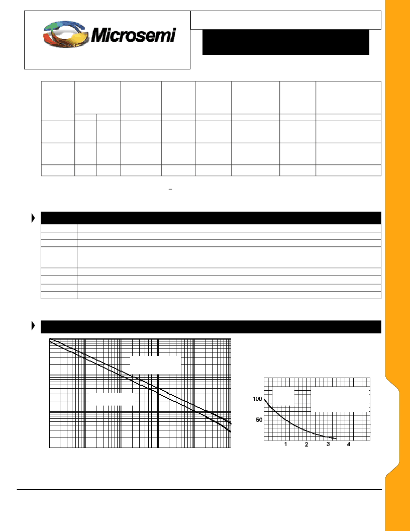
GRAPHS
Definition
V
C
FIG. 2
Pulse wave form for exponential surge
100ns
1
μ
s
10
μ
s
100
μ
s
1ms
10ms
P
P
)
P
Square-wave pulse
Exponential wave-form
(See FIG. 2)
P
P
)
Peak Value
I
PP
Pulse time duration (tp) is
defined as that point where
I
P
decays to 50% of peak
value (I
PP
).
time (t) in milliseconds
Pulse Time (tp)
FIG. 1 –
Non-repetive peak pulse power rating curve
NOTE: Peak power defined as peak voltage times peak current
相关PDF资料 |
PDF描述 |
|---|---|
| JAN1N5629 | 1500 WATT UNIDIRECTIONAL TRANSIENT VOLTAGE SUPPRESSOR |
| JAN1N5629A | 1500 WATT UNIDIRECTIONAL TRANSIENT VOLTAGE SUPPRESSOR |
| JAN1N5630 | 1500 WATT UNIDIRECTIONAL TRANSIENT VOLTAGE SUPPRESSOR |
| JAN1N5630A | 1500 WATT UNIDIRECTIONAL TRANSIENT VOLTAGE SUPPRESSOR |
| JAN1N5631 | 1500 WATT UNIDIRECTIONAL TRANSIENT VOLTAGE SUPPRESSOR |
相关代理商/技术参数 |
参数描述 |
|---|---|
| JAN1N5641A | 制造商:Microsemi Corporation 功能描述:TVS SGL UNI-DIR 18.8V 1.5KW 2PIN DO-13 - Bulk |
| JAN1N5642A | 制造商:Microsemi Corporation 功能描述:TVS SGL UNI-DIR 20.5V 1.5KW 2PIN DO-13 - Bulk |
| JAN1N5643A | 制造商:Microsemi Corporation 功能描述:TVS SGL UNI-DIR 23.1V 1.5KW 2PIN DO-13 - Bulk |
| JAN1N5644A | 制造商:Microsemi Corporation 功能描述:Diode TVS Single Uni-Dir 25.6V 1.5KW 2-Pin DO-13 制造商:Microsemi Corporation 功能描述:TVS SGL UNI-DIR 25.6V 1.5KW 2PIN DO-13 - Bulk |
| JAN1N5645A | 制造商:Microsemi Corporation 功能描述:TVS SGL UNI-DIR 28.2V 1.5KW 2PIN DO-13 - Bulk |
发布紧急采购,3分钟左右您将得到回复。