- 您现在的位置:买卖IC网 > PDF目录296295 > KS2603SBK5N6J (KOA SPEER ELECTRONICS INC) 1 ELEMENT, 0.0056 uH, AIR-CORE, GENERAL PURPOSE INDUCTOR, SMD PDF资料下载
参数资料
| 型号: | KS2603SBK5N6J |
| 厂商: | KOA SPEER ELECTRONICS INC |
| 元件分类: | 通用定值电感 |
| 英文描述: | 1 ELEMENT, 0.0056 uH, AIR-CORE, GENERAL PURPOSE INDUCTOR, SMD |
| 封装: | LEAD FREE |
| 文件页数: | 1/1页 |
| 文件大小: | 101K |
| 代理商: | KS2603SBK5N6J |
TECHNOLOGY OF TOMORROW
INDUCTORS
Revision: 5. Nov. 2004
EUROPE GmbH Kaddenbusch 6 D-25578 Dgeling / ITZEHOE PHONE: +49 (0) 48 21 / 89 89-0 FAX: +49 (0) 48 21/ 89 89 89 Internet: www.koaeurope.de
Specifications
given
herein
may
be
changed
at
any
time
without
prior
notice.
Please
confirm
technical
specifications
before
you
order
and/or
use.
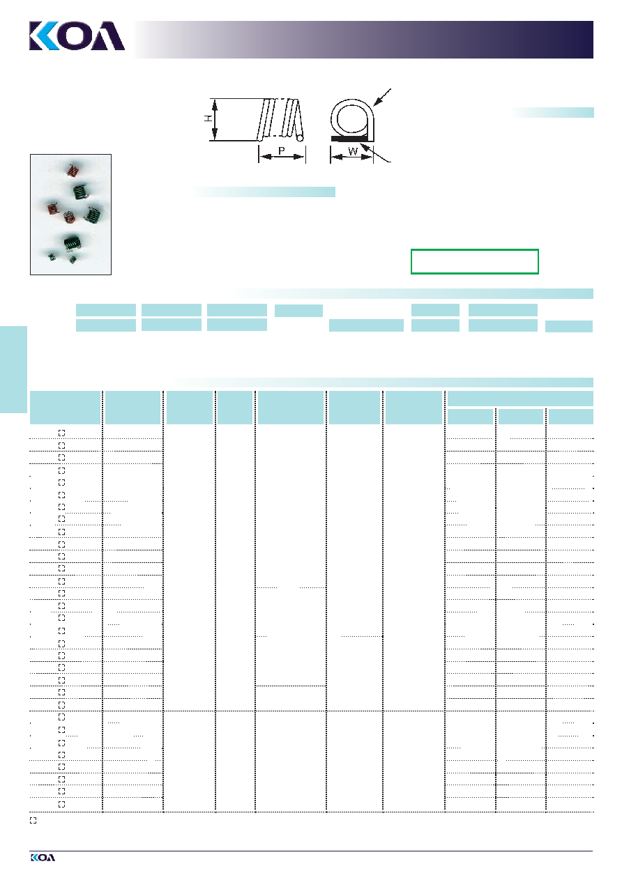
INDUCTORS
AIR CORE
SPRING COIL
KS
FEATURES
■ Low DC resistance and large allowable current
■ Mountable spring type inductors with extremely high Q
■ High SRF and excellent high frequency characteristics
■ Space saving electrode position structure
■ The small dimensions allow high density mounting
■ Customer specific spring coils on request
■ Operating temperature range: - 40° C ... + 125° C
■ Suitable for reflow soldering
TYPE
NOMINAL
INDUCTANCE
TOLERANCE
QUALITY
FACTOR
(MIN.)
SELF RESONANT
FREQUENCY
(MIN.)
DC
RESISTANCE
(MAX.)
ALLOWABLE
DC CURRENT
(MAX.)
P
DIMENSIONS (mm)
W
H
RATING AND DIMENSIONS
KS2004
TE 5N6
■
5.6 nH
1.15 ± 0.1
1.05 ± 0.1
1.30 ± 0.1
KS2004
TE 9N1
■
9.1 nH
100
5.0 GHz
10 m
1.5 A
1.15 ± 0.1
1.25 ± 0.1
1.50 ± 0.1
KS2004
TE 10N
■
10 nH
1.15 ± 0.1
1.35 ± 0.1
1.60 ± 0.1
KS2004
TE 12N
■
12 nH
1.15 ± 0.1
1.45 ± 0.1
1.70 ± 0.1
KS2603
TE 3N6
■
3.6 nH
1.15 ± 0.1
1.20 ± 0.1
1.50 ± 0.1
KS2603
TE 5N6
■
5.6 nH
1.15 ± 0.1
1.40 ± 0.1
1.70 ± 0.1
KS2604
TE 5N1
■
5.1 nH
1.40 ± 0.1
1.20 ± 0.1
1.50 ± 0.1
KS2604
TE 6N2
■
6.2 nH
1.40 ± 0.1
1.30 ± 0.1
1.60 ± 0.1
KS2604
TE 7N5
■
7.5 nH
5.0 GHz
1.40 ± 0.1
1.70 ± 0.1
KS2604
TE 9N1
■
9.1 nH
1.40 ± 0.1
1.50 ± 0.1
1.80 ± 0.1
KS2604
TE 11N
■
11 nH
20 m
1.40 ± 0.1
1.60 ± 0.1
1.90 ± 0.1
KS2604
TE 12N
■
12 nH
1.40 ± 0.1
1.70 ± 0.1
2.00 ± 0.1
KS2604
TE 15N
■
15 nH
1.40 ± 0.1
1.80 ± 0.1
2.10 ± 0.1
KS2605
TE 10N
■
10 nH
100
2.0 A
1.70 ± 0.1
1.40 ± 0.1
1.70 ± 0.1
KS2605
TE 13N
■
13 nH
3.0 GHz
1.70 ± 0.1
1.50 ± 0.1
1.80 ± 0.1
KS2605
TE 15N
■
15 nH
1.70 ± 0.1
1.60 ± 0.1
1.90 ± 0.1
KS2605
TE 18N
■
18 nH
1.70 ± 0.1
2.00 ± 0.1
KS2606
TE 20N
■
20 nH
2.00 ± 0.1
1.60 ± 0.1
1.90 ± 0.1
KS2606
TE 22N
■
22 nH
2.0 GHz
2.00 ± 0.1
1.70 ± 0.1
2.00 ± 0.1
KS2606
TE 24N
■
24 nH
40 m
2.00 ± 0.1
1.80 ± 0.1
2.10 ± 0.1
KS2607
TE 27N
■
27 nH
2.30 ± 0.1
1.70 ± 0.1
2.00 ± 0.1
KS2609
TE 24N
■
24 nH
3.0 GHz
2.90 ± 0.1
1.50 ± 0.1
1.80 ± 0.1
KS2609
TE 30N
■
30 nH
2.90 ± 0.1
1.60 ± 0.1
1.90 ± 0.1
KS3004
TE 10N
■
10 nH
1.70 ± 0.1
1.65 ± 0.1
2.00 ± 0.1
KS3005
TE 11N
■
11 nH
2.00 ± 0.1
1.55 ± 0.1
1.90 ± 0.1
KS3006
TE 15N
■
15 nH
2.30 ± 0.1
1.55 ± 0.1
1.90 ± 0.1
KS3006
TE 18N
■
18 nH
100
3.0 GHz
20 m
2.5 A
2.30 ± 0.1
1.65 ± 0.1
2.00 ± 0.1
KS3006
TE 22N
■
22 nH
2.30 ± 0.1
1.85 ± 0.1
2.20 ± 0.1
KS3006
TE 30N
■
30 nH
2.30 ± 0.1
2.05 ± 0.1
2.40 ± 0.1
KS3007
TE 16N
■
16 nH
2.65 ± 0.1
1.55 ± 0.1
1.90 ± 0.1
KS3007
TE 33N
■
33 nH
2.65 ± 0.1
1.95 ± 0.1
2.30 ± 0.1
J (± 5%)
K (± 10%)
J (± 5%)
K (± 10%)
J (± 5%)
K (± 10%)
1 Magnet wire
2 Solder plating
STRUCTURE
1
2
Products with Pb-free terminations
meet RoHS requirements
TYPE DESIGNATION (HOW TO ORDER)
*Please see “PACKAGING”
KS
PRODUCT CODE
TE
TAPING*
TE, BK
5N6
NOMINAL
INDUCTANCE
3 digits code
(see rating table)
TERMINATION
SURFACE MATERIAL
T: Sn
S: Ag
L: Sn/Pb
20
WIRE DIAMETER
(20 v 0.2 mm)
(26 v 0.26 mm)
(30 v 0.3 mm)
KS
TE
5N6
T
J
INDUCTANCE
TOLERANCE
J: ±5%
K: ±10%
20
04
TURN NUMBER
(03, 04, 05,
06, 07, 09)
J
INDUCTANCE
TOLERANCE
Enter the code for termination surface material (T, S, L)
Measuring frequency: 800 MHz
■
Enter the code for inductance tolerance (J, K)
The above mentioned characteristic values are representative examples and can be changed according to the customer`s requirements.
Old Part No.
New Part No.
(Pb-free)
相关PDF资料 |
PDF描述 |
|---|---|
| KS2605SBK15NK | 1 ELEMENT, 0.015 uH, AIR-CORE, GENERAL PURPOSE INDUCTOR, SMD |
| KS3004TBK10NK | 1 ELEMENT, 0.01 uH, AIR-CORE, GENERAL PURPOSE INDUCTOR, SMD |
| KS3006SBK22NJ | 1 ELEMENT, 0.022 uH, AIR-CORE, GENERAL PURPOSE INDUCTOR, SMD |
| KSC441JST2LFS | KEYPAD SWITCH, SPST, MOMENTARY-TACTILE, 0.05A, 32VDC, 4.4 N, SURFACE MOUNT-STRAIGHT |
| KSC461JST2LFS | KEYPAD SWITCH, SPST, MOMENTARY-TACTILE, 0.05A, 32VDC, 8 N, SURFACE MOUNT-STRAIGHT |
相关代理商/技术参数 |
参数描述 |
|---|---|
| KS2607TTE27NJ | 制造商:KOA Speer Electronics Inc 功能描述:27nH 2.0A SM IND-SPRING CHIP 5% 100% Tin RoHS 制造商:KOA Speer Electronics Inc 功能描述:27nH 2.0A SM IND-SPRING CHIP 5% 100% Tin RoHS - free partial T/R at 500. |
| KS2609TTE24NJ | 制造商:KOA Speer Electronics Inc 功能描述:24nH 2.0A SM IND-SPRING CHIP 5% 100% Tin RoHS 制造商:KOA Speer Electronics Inc 功能描述:24nH 2.0A SM IND-SPRING CHIP 5% 100% Tin RoHS - free partial T/R at 500. |
| KS2609TTE30NJ | 制造商:KOA Speer Electronics Inc 功能描述:30nH 2.0A SM IND-SPRING CHIP 5% 100% Tin RoHS 制造商:KOA Speer Electronics Inc 功能描述:30nH 2.0A SM IND-SPRING CHIP 5% 100% Tin RoHS - free partial T/R at 500. |
| KS29.1-1000E | 制造商:Austerlitz Electronic 功能描述:Bulk |
| KS29.1-50E MKB | 制造商:Austerlitz Electronic 功能描述: |
发布紧急采购,3分钟左右您将得到回复。