- 您现在的位置:买卖IC网 > PDF目录262304 > KT11B2SM (C K COMPONENTS INC) KEYPAD SWITCH, SPST, MOMENTARY, 0.02A, 50VDC, SURFACE MOUNT-STRAIGHT PDF资料下载
参数资料
| 型号: | KT11B2SM |
| 厂商: | C K COMPONENTS INC |
| 元件分类: | 开关 |
| 英文描述: | KEYPAD SWITCH, SPST, MOMENTARY, 0.02A, 50VDC, SURFACE MOUNT-STRAIGHT |
| 文件页数: | 1/3页 |
| 文件大小: | 418K |
| 代理商: | KT11B2SM |
KT11B0CM
MOM. = Momentary
With B1 Silicone
Rubber Actuator
With B2 Silicone
Rubber Actuator
With P2 Hard
Plastic Actuator
With P3 Hard
Plastic Actuator
With P4 Hard
Plastic Actuator
PC MOUNTING
Features/Benefits
Typical Applications
S Internal actuator seal and insert molded terminals—
permit soldering and cleaning
S Tin-lead plated terminals—improves solderability
S Tape and reel packaging available
S Right angle surface mount models available
S Telecommunications
S Computer Products
S Instrumentation
SPST
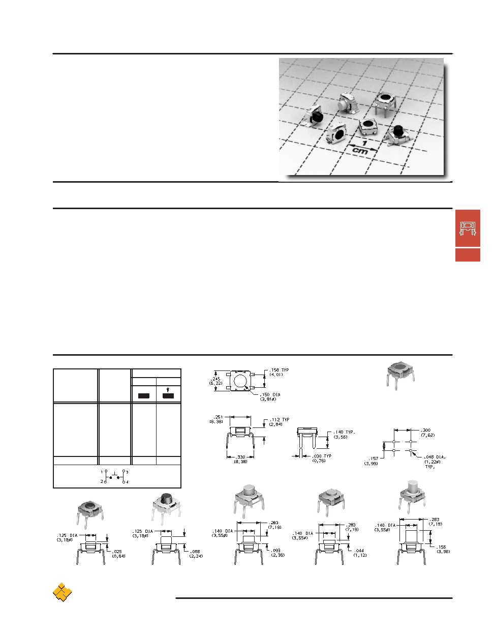
Sealed Tactile Switches
C&K KT Series
T
actile
C
C-3
www.ittcannon.com
ITT Industries
Cannon
How To Order
Complete part numbers for KT Series Sealed Tactile Switches are shown on pages C-3 thru C-5.
Specifications
CONTACT RATING: 1.0 VA max. @ 50 V AC or DC max.
MECHANICAL & ELECTRICAL LIFE: 100,000 make-and-break
cycles at full load.
CONTACT RESISTANCE: Below 50 milliohms typ. initial @
2-4 V DC, 100 mA.
INSULATION RESISTANCE: 109 ohms min.
DIELECTRIC STRENGTH: 250 V RMS min. @ sea level.
OPERATING TEMPERATURE: –40
_C to 90_C.
SOLDERABILITY: Per MIL-STD-202F method 208D, or
EIA RS-186E method 9 (1 hour steam aging).
DEGREE OF PROTECTION: IP57; Protection against harmful dust
deposit, full-scale voltage protection, temporary immersion.
PACKAGING: Switches supplied in rigid dispensing tubes
or anti-static tape and reels per EIA 481-2, see pages
L-36 and L-37 for drawings and reel information. Tape and
cover strip are conductive for use near statically sensitive
components, consult Customer Service Center.
Materials
HOUSING: Stainless steel.
BASE: LCP or PPA (UL 94V-0).
ACTUATOR: B0, B1, B2 actuators: Silicone rubber.
P2, P3, P4 actuators: Nylon (UL 94V-0).
MOVABLE CONTACT: Stainless steel, silver plated.
STATIONARY CONTACTS: Copper alloy, silver plate over nickel.
TERMINALS: Copper alloy, with tin-lead alloy over nickel plate.
All terminals insert molded.
SEAL: Silicone rubber (UL 94V-0).
NOTE: Specifications and materials listed above are general specifications for switches
with standard options. For information on specific and custom switches, consult Customer
Service Center.
CAUTION: PC mounting layouts and pads as shown are designed to be compatible with the
latest equipment and reflow techniques. Care should be taken in the design and location of
PC lands to suit individual needs. Orientation relative to reflow direction may significantly
impact solder joint integrity.
6.22 x 6.38mm Models
SWITCH FUNCTION
POS. 1
POS. 2
PART NUMBER
ACTUATOR
HEIGHT
KT11B0CM
FLUSH
OFF
MOM.
KT11B1CM
.025 (0,64)
OFF
MOM.
KT11B2CM
.088 (2,24)
OFF
MOM.
KT11P2CM
.093 (2,36)
OFF
MOM.
KT11P3CM
.044 (1,12)
OFF
MOM.
KT11P4CM
.156 (3,96)
OFF
MOM.
Conn. Terms
OPEN
1,2-3,4
Schematic
SPST
相关PDF资料 |
PDF描述 |
|---|---|
| K12AGY1.53.5N | KEYPAD SWITCH, SPST, MOMENTARY-TACTILE, 0.1A, 30VDC, 3.5 N, THROUGH HOLE-STRAIGHT |
| K12AGY25N | KEYPAD SWITCH, SPST, MOMENTARY-TACTILE, 0.1A, 30VDC, 5 N, THROUGH HOLE-STRAIGHT |
| K12ALGN1.51.5NODL306 | KEYPAD SWITCH, SPST, MOMENTARY-TACTILE, 0.1A, 30VDC, 1.5 N, THROUGH HOLE-STRAIGHT |
| K12PLRD1.52.5NL3521R | KEYPAD SWITCH, SPST, MOMENTARY-TACTILE, 0.1A, 30VDC, 2.5 N, THROUGH HOLE-STRAIGHT |
| K12PYE1.52.5N | KEYPAD SWITCH, SPST, MOMENTARY-TACTILE, 0.1A, 30VDC, 2.5 N, THROUGH HOLE-STRAIGHT |
相关代理商/技术参数 |
参数描述 |
|---|---|
| KT11B2SM34 LFS | 制造商:C&K Components 功能描述: 制造商:C&K Components 功能描述:SWITCH TACTILE SPST-NO 1VA 32V |
| KT11B2SM34LFS | 功能描述:触觉开关 2.24Mm Silv Gwing RoHS:否 制造商:C&K Components 工作力:2 N 执行器:Round 电流额定值:50 mA 电压额定值 DC:32 V 电压额定值 AC: 功率额定值:1 VA 接地端子:Yes 触点形式:SPST-NO 开关功能: 安装风格:SMD/SMT 安装方向:Right 晶体管管座高度: 颜色: 照明:Not Illuminated 照明颜色: 封装: |
| KT11BOSAM34LFS | 制造商: 功能描述: 制造商:undefined 功能描述: |
| KT-11D-12 | 制造商:TE Connectivity 功能描述: |
| KT11JM34LFG | 制造商:CK-COMPONENTS 制造商全称:C&K Components 功能描述:Right Angle Sealed Tact Switch for SMT |
发布紧急采购,3分钟左右您将得到回复。