- 您现在的位置:买卖IC网 > PDF目录30713 > L64733C-48 (LSI CORP) SPECIALTY CONSUMER CIRCUIT, PQFP48 PDF资料下载
参数资料
| 型号: | L64733C-48 |
| 厂商: | LSI CORP |
| 元件分类: | 消费家电 |
| 英文描述: | SPECIALTY CONSUMER CIRCUIT, PQFP48 |
| 封装: | TQFP-48 |
| 文件页数: | 22/52页 |
| 文件大小: | 552K |
| 代理商: | L64733C-48 |
第1页第2页第3页第4页第5页第6页第7页第8页第9页第10页第11页第12页第13页第14页第15页第16页第17页第18页第19页第20页第21页当前第22页第23页第24页第25页第26页第27页第28页第29页第30页第31页第32页第33页第34页第35页第36页第37页第38页第39页第40页第41页第42页第43页第44页第45页第46页第47页第48页第49页第50页第51页第52页
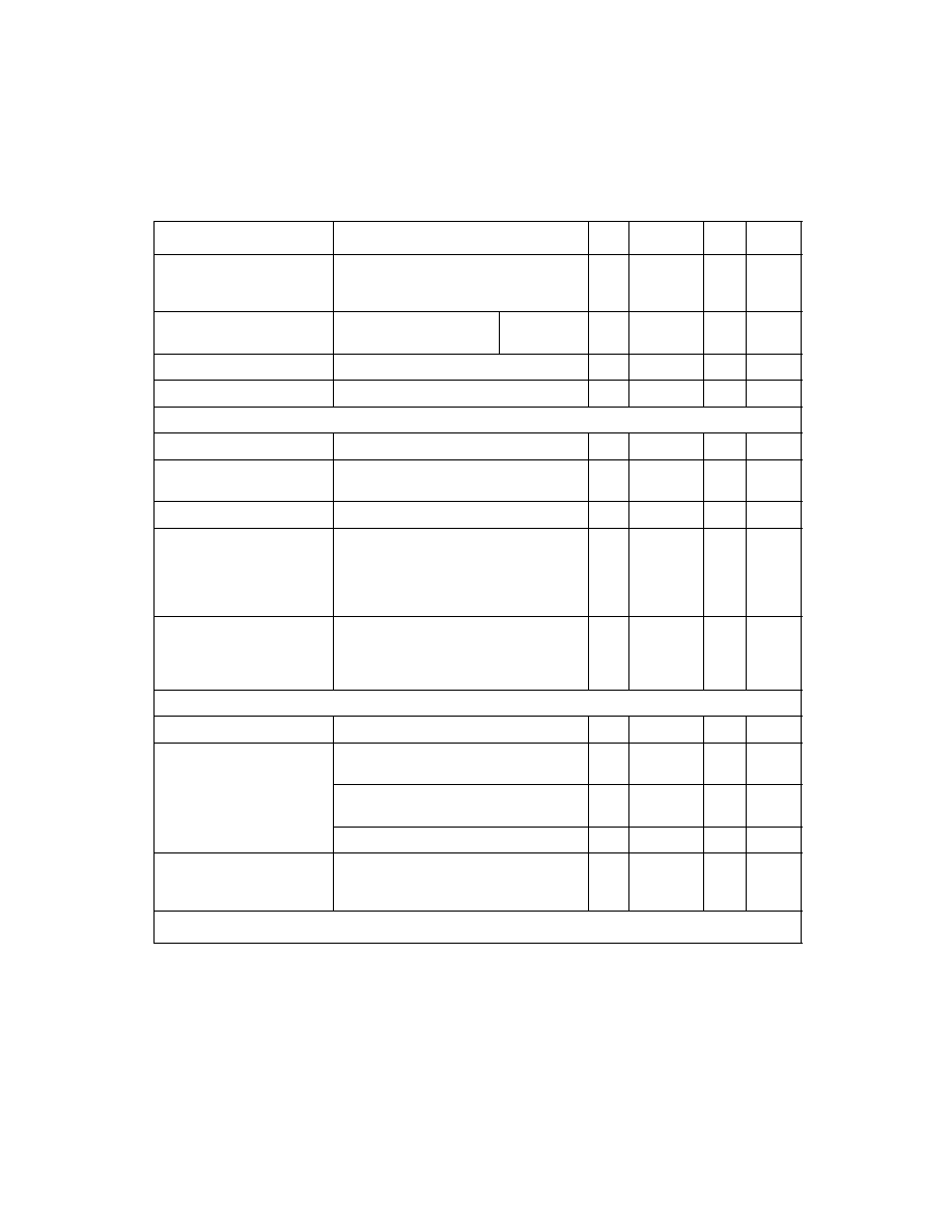
L64733C/L64734 Tuner and Satellite Receiver Chipset
29
Baseband Frequency
Response
Deviation from ideal 7th-order
Butterworth, measure to F
3 dB x 0.7.
Include front-end tilt effects
0.5
–
0.5
dB
LPF Cutoff Frequency
Accuracy
Measured
3 dB point.
@8 MHz
@31.4 MHz
5.5
10
–
5.5
10
%
Quadrature Gain Error
Includes effects from baseband lters
–
1.2
dB
Quadrature Phase Error
Measure at 125 kHz
–
4
Deg
Synthesizer
Crystal Frequency Range
4
–
7.26
MHz
XTLOUT Voltage Levels
Measured on 10 pF in parallel with
1M
0.75
1.0
1.5
Vpp
XTLOUT DC Level
–
2.0
–
V
MODp, MODn Delay
Must assert MOD level within this time
period to ensure that the next PSOUT
period gives correct count. Delay is
with respect to rising edge of PSOUT
(previous count).
–
7
nsec
PLLINp, PLLINn and
MODp, MODn Hold Time
With respect to rising edge of PSOUT.
This means that PSOUT need not con-
tinue to be asserted after MOD has
given correct count.
0
–
nsec
Local Oscillator
LO Tuning Range
543
–
1180
MHz
LO Phase Noise, Including
Doubler. Subject to LC tank
implementation.
1 kHz offset. Depends on PLL loop
gain.
–
55
–
dBc/Hz
10 kHz offset. Depends on PLL loop
gain.
–
75
–
dBc/Hz
100 kHz offset
–
95
–
dBc/Hz
LO Buffer Frequency
Range when overdriven by
external LO
FDOUB = low
925
–
2175
MHz
1.
For symbol rates below 15 MS/s, the maximum input power might be subject to shifting down by
roughly 10 * log(15/Rs[MS/s]) dB due to channel bandwidth reduction.
2.
x 1.5 harmonic rejection for FLO = 725 MHz.
Table 4
AC Characteristics of the L64733C (Cont.)
Parameter
Condition
Min
Typ
Max
Units
(Sheet 3 of 3)
相关PDF资料 |
PDF描述 |
|---|---|
| L64781 | SPECIALTY CONSUMER CIRCUIT, PQFP100 |
| L6561 | 0.7 A POWER FACTOR CONTROLLER, PDIP8 |
| L6566ATR | 0.8 A POWER FACTOR CONTROLLER WITH POST REGULATOR, 300 kHz SWITCHING FREQ-MAX, PDSO16 |
| L6605D | SPECIALTY CONSUMER CIRCUIT, PDSO20 |
| L6605 | SPECIALTY CONSUMER CIRCUIT, PDIP18 |
相关代理商/技术参数 |
参数描述 |
|---|---|
| L64734 | 制造商:LSI 制造商全称:LSI 功能描述:Tuner and Satellite Receiver Chipset |
| L64734C-45 | 制造商:LSI 功能描述: 制造商:LSI Corporation 功能描述: |
| L64735GM-20 | 制造商:未知厂家 制造商全称:未知厂家 功能描述:Image Processor |
| L64735GM-27 | 制造商:未知厂家 制造商全称:未知厂家 功能描述:Image Processor |
| L64735GM-35 | 制造商:未知厂家 制造商全称:未知厂家 功能描述:Image Processor |
发布紧急采购,3分钟左右您将得到回复。