- 您现在的位置:买卖IC网 > PDF目录43900 > L6712DTR (STMICROELECTRONICS) 2 A SWITCHING CONTROLLER, PDSO28 PDF资料下载
参数资料
| 型号: | L6712DTR |
| 厂商: | STMICROELECTRONICS |
| 元件分类: | 稳压器 |
| 英文描述: | 2 A SWITCHING CONTROLLER, PDSO28 |
| 封装: | SO-28 |
| 文件页数: | 6/29页 |
| 文件大小: | 624K |
| 代理商: | L6712DTR |
第1页第2页第3页第4页第5页当前第6页第7页第8页第9页第10页第11页第12页第13页第14页第15页第16页第17页第18页第19页第20页第21页第22页第23页第24页第25页第26页第27页第28页第29页
L6712A L6712
14/29
usual way until another OCP event is detected.
This means that the average current delivered can slightly increase also in Over Current condition since
the current ripple increases. In fact, the ON time increases due to the OFF time rise because of the current
has to reach the IOCPx bottom. The worst-case condition is when the ON time reaches its maximum value.
When this happens, the device works in Constant Current and the output voltage decrease as the load
increase. Crossing the UVP threshold causes the device to reset.
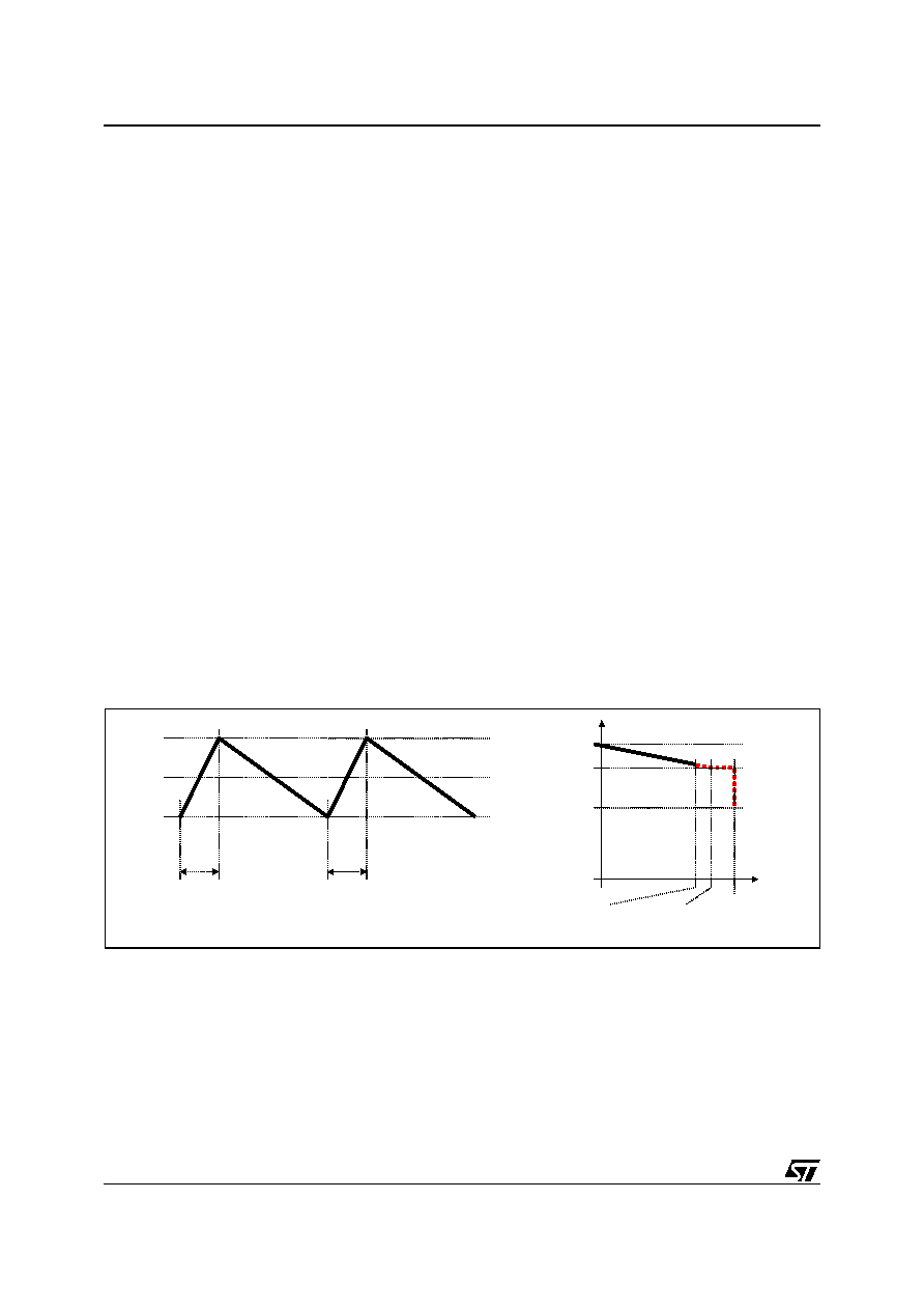
Figure 10 shows this working condition.
It can be observed that the peak current (Ipeak) is greater than the IOCPx but it can be determined as follow:
Where VoutMIN is the minimum output voltage (VID-40% as follow).
The device works in Constant-Current, and the output voltage decreases as the load increase, until the
output voltage reaches the under-voltage threshold (VoutMIN).
The maximum average current during the Constant-Current behavior results:
In this particular situation, the switching frequency results reduced. The ON time is the maximum allowed
(TonMAX) while the OFF time depends on the application:
Figure 10. Constant Current operation
Over current is set anyway when IINFOx reaches 35A (IFB=70A). The full load value is only a convention
to work with convenient values for IFB. Since the OCP intervention threshold is fixed, to modify the per-
centage with respect to the load value, it can be simply considered that, for example, to have on OCP
threshold of 200%, this will correspond to IINFOx = 35A (IFB = 70A). The full load current will then corre-
spond to IINFOx = 17.5A (IFB = 35A).
Once the UVP threshold has been intercepted, the device resets with all power mosfets turned OFF. An-
other soft start is then performed allowing the device to recover from OCP once the over load cause has
been removed.
Crossing the UVP threshold causes the device to reset: all mosfets are turned off and a new soft start is
I
peak
I
OCPx
V
IN
Vout
min
–
L
-------------------------------------- Ton
MAX
I
OCPx
V
IN
Vout
MIN
–
L
--------------------------------------- 0.40 T
+
=
+
=
I
MAX,TOT
2I
MAX
2I
OCPx
Ipeak
I
OCPx
–
2
--------------------------------------
+
=
=
T
OFF
L
Ipeak
I
OCPx
–
V
OUt
--------------------------------------
f
1
T
ONmax
T
OFF
+
------------------------------------------
=
=
a) Maximum current for each phase
b) Output Characteristic
TonMAX
IOCPx
Ipeak
IMAX
Vout
Iout
(IDROOP=50A)
2IOCPx (IDROOP=70A)
IMAX,TOT
UVP
Droop effect
相关PDF资料 |
PDF描述 |
|---|---|
| L6712Q | 2 A SWITCHING CONTROLLER, QCC36 |
| L6712ADTR | 2 A SWITCHING CONTROLLER, PDSO28 |
| L6712D | 2 A SWITCHING CONTROLLER, PDSO28 |
| L6712QTR | 2 A SWITCHING CONTROLLER, QCC36 |
| L6725ATR | 20 A SWITCHING CONTROLLER, 500 kHz SWITCHING FREQ-MAX, PDSO16 |
相关代理商/技术参数 |
参数描述 |
|---|---|
| L6712Q | 功能描述:开关变换器、稳压器与控制器 2-Ph Interleaved RoHS:否 制造商:Texas Instruments 输出电压:1.2 V to 10 V 输出电流:300 mA 输出功率: 输入电压:3 V to 17 V 开关频率:1 MHz 工作温度范围: 安装风格:SMD/SMT 封装 / 箱体:WSON-8 封装:Reel |
| L6712QTR | 功能描述:开关变换器、稳压器与控制器 2-Ph Interleaved RoHS:否 制造商:Texas Instruments 输出电压:1.2 V to 10 V 输出电流:300 mA 输出功率: 输入电压:3 V to 17 V 开关频率:1 MHz 工作温度范围: 安装风格:SMD/SMT 封装 / 箱体:WSON-8 封装:Reel |
| L6712大电流DCDC转换器 | 制造商:未知厂家 制造商全称:未知厂家 功能描述: |
| L6713A | 功能描述:DC/DC 开关控制器 2/3 Phase controller RoHS:否 制造商:Texas Instruments 输入电压:6 V to 100 V 开关频率: 输出电压:1.215 V to 80 V 输出电流:3.5 A 输出端数量:1 最大工作温度:+ 125 C 安装风格: 封装 / 箱体:CPAK |
| L6713A_0805 | 制造商:STMICROELECTRONICS 制造商全称:STMicroelectronics 功能描述:2/3/4 phase controller with embedded drivers for Intel VR11.1 |
发布紧急采购,3分钟左右您将得到回复。