- 您现在的位置:买卖IC网 > PDF目录43900 > L6727TR (STMICROELECTRONICS) 1.5 A SWITCHING CONTROLLER, 350 kHz SWITCHING FREQ-MAX, PDSO8 PDF资料下载
参数资料
| 型号: | L6727TR |
| 厂商: | STMICROELECTRONICS |
| 元件分类: | 稳压器 |
| 英文描述: | 1.5 A SWITCHING CONTROLLER, 350 kHz SWITCHING FREQ-MAX, PDSO8 |
| 封装: | LEAD FREE, SOP-8 |
| 文件页数: | 10/34页 |
| 文件大小: | 974K |
| 代理商: | L6727TR |
第1页第2页第3页第4页第5页第6页第7页第8页第9页当前第10页第11页第12页第13页第14页第15页第16页第17页第18页第19页第20页第21页第22页第23页第24页第25页第26页第27页第28页第29页第30页第31页第32页第33页第34页
Application details
L6727
18/34
Doc ID 12933 Rev 4
same high-current trace on more than one PCB layer will reduce the parasitic resistance
associated to that connection.
Connect output bulk capacitors (COUT) as near as possible to the load, minimizing parasitic
inductance and resistance associated to the copper trace, also adding extra decoupling
capacitors along the way to the load when this results in being far from the bulk capacitors
bank.
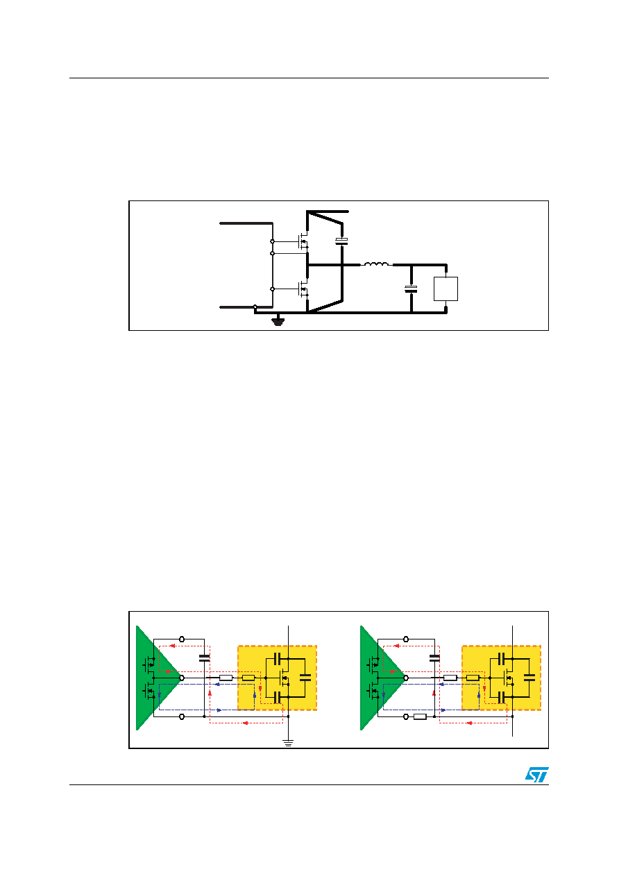
Figure 8.
Power connections (heavy lines)
Gate traces and phase trace must be sized according to the driver RMS current delivered to
the power MOSFET. The device robustness allows managing applications with the power
section far from the controller without losing performances. Anyway, when possible, it is
recommended to minimize the distance between controller and power section. See Figure 9
for drivers current paths.
Small signal components and connections to critical nodes of the application, as well as
bypass capacitors for the device supply, are also important. Locate bypass capacitor (VCC
and Bootstrap capacitor) and loop compensation components as close to the device as
practical. For over current programmability, place ROCSET close to the device and avoid
leakage current paths on COMP / OC pin, since the internal current source is only 60
μA.
Systems that do not use Schottky diode in parallel to the Low-Side MOSFET might show big
negative spikes on the phase pin. This spike must be limited within the absolute maximum
ratings (for example, adding a gate resistor in series to HS MOSFET gate, or a phase
resistor in series to PHASE pin), as well as the positive spike, but has an additional
consequence: it causes the bootstrap capacitor to be over-charged. This extra-charge can
cause, in the worst case condition of maximum input voltage and during particular
transients, that boot-to-phase voltage overcomes the absolute maximum ratings also
causing device failures. It is then suggested in this cases to limit this extra-charge by adding
Figure 9.
Drivers turn-on and turn-off paths
L
CIN
VIN
UGATE
PHASE
LGATE
GND
LOAD
L6727
COUT
RGATE
RINT
CGD
CGS
CDS
VCC
LS DRIVER
LS MOSFET
GND
LGATE
RGATE
RINT
CGD
CGS
CDS
BOOT
HS DRIVER
HS MOSFET
PHASE
UGATE
RPHASE
相关PDF资料 |
PDF描述 |
|---|---|
| L6727 | 1.5 A SWITCHING CONTROLLER, 350 kHz SWITCHING FREQ-MAX, PDSO8 |
| L6728AHTR | SWITCHING CONTROLLER, PDSO10 |
| L6730DTR | 20 A SWITCHING CONTROLLER, 1000 kHz SWITCHING FREQ-MAX, PDSO20 |
| L6730D | 20 A SWITCHING CONTROLLER, 1000 kHz SWITCHING FREQ-MAX, PDSO20 |
| L6730CQTR | 20 A SWITCHING CONTROLLER, 1000 kHz SWITCHING FREQ-MAX, QCC24 |
相关代理商/技术参数 |
参数描述 |
|---|---|
| L6728 | 功能描述:DC/DC 开关控制器 Sngl phase PWM controller RoHS:否 制造商:Texas Instruments 输入电压:6 V to 100 V 开关频率: 输出电压:1.215 V to 80 V 输出电流:3.5 A 输出端数量:1 最大工作温度:+ 125 C 安装风格: 封装 / 箱体:CPAK |
| L6728_0706 | 制造商:STMICROELECTRONICS 制造商全称:STMicroelectronics 功能描述:Single phase PWM controller with Power Good |
| L6728A | 功能描述:电压模式 PWM 控制器 Hi-Freq. singl-phase PWM controller w/Po RoHS:否 制造商:Texas Instruments 输出端数量:1 拓扑结构:Buck 输出电压:34 V 输出电流: 开关频率: 工作电源电压:4.5 V to 5.5 V 电源电流:600 uA 最大工作温度:+ 125 C 最小工作温度:- 40 C 封装 / 箱体:WSON-8 封装:Reel |
| L6728AH | 功能描述:软开关 PWM 控制器 Sgl Output 600 KHz DFPN-10 RoHS:否 制造商:Fairchild Semiconductor 输出端数量: 输出电流: 开关频率: 工作电源电压:30 V 电源电流: 最大工作温度:+ 105 C 最小工作温度:- 40 C 安装风格:SMD/SMT 封装 / 箱体:SOIC-8 封装:Reel |
| L6728AHTR | 功能描述:电流型 PWM 控制器 HIGH FREQ PWM CNTRL W/PO RoHS:否 制造商:Texas Instruments 开关频率:27 KHz 上升时间: 下降时间: 工作电源电压:6 V to 15 V 工作电源电流:1.5 mA 输出端数量:1 最大工作温度:+ 105 C 安装风格:SMD/SMT 封装 / 箱体:TSSOP-14 |
发布紧急采购,3分钟左右您将得到回复。