- 您现在的位置:买卖IC网 > PDF目录43901 > L6788ATR (STMICROELECTRONICS) 3-CHANNEL POWER SUPPLY SUPPORT CKT, QCC40 PDF资料下载
参数资料
| 型号: | L6788ATR |
| 厂商: | STMICROELECTRONICS |
| 元件分类: | 电源管理 |
| 英文描述: | 3-CHANNEL POWER SUPPLY SUPPORT CKT, QCC40 |
| 封装: | 6 X 6 MM, 1 MM HEIGHT, ROHS COMPLIANT, VFQFN-40 |
| 文件页数: | 3/18页 |
| 文件大小: | 330K |
| 代理商: | L6788ATR |
L6788A
Electrical specifications
Doc ID 15341 Rev 2
11/18
4
Electrical specifications
4.1
Electrical characteristics
VCC = 12 V ± 15%, TJ = 25 °C unless otherwise specified.
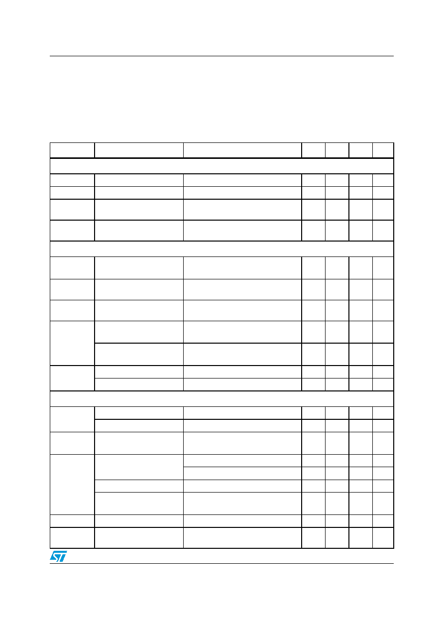
Table 5.
Electrical characteristics
Symbol
Parameter
Test condition
Min.
Typ.
Max.
Unit
Supply voltages operating conditions
VCC1_IC
Device supply voltage
10.8
12
13.2
V
VCC2_DR
LS driver supply voltage
10.8
12
13.2
V
Vsuorces
(VIN)
Conversion input voltage
Vsource1 = Vsource2
10.8
13.2
V
Vsource1-
Vsource2
BOOTx supply current
Max difference between conversion
input voltages (static condition)
2.4
V
Supply current and power-on
ICC1_IC
VCC1_IC supply current
UGATEx and LGATEx OPEN;
VCC1_IC=VCC2_DR=VBOOTx=12 V
25
mA
ICC2_DR
VCC2_DR supply current
LGATEx = OPEN;
VCC1_IC=VCC2_DR= 12 V
6mA
IBOOTx
BOOTx supply current
UGATEx = OPEN; PHASEx to PGND;
VCC1_IC=VCC2_DR=BOOTx=12 V
2mA
UVLOVCC_IC
VCC1_IC turn-ON threshold
VCC1_IC rising;
VCC2_DR = VCC1_IC
7V
VCC1_IC turn-OFF
threshold
VCC1_IC falling;
VCC2_DR = VCC1_IC
5.8
V
UVLO5VCC
5VCC turn-ON threshold
5 VCC rising; VCC1_IC=VCC2_DR>7
3
V
5VCC turn-OFF threshold
5 VCC falling; VCC1_IC=VCC2_DR>7
1
V
Oscillator, soft start time and inhibit
FOSC
Default value
RT = OPEN
200
kHz
Programmability range
RT connected to AGND
200
800
kHz
Trp
Soft start time
VCC1_IC = 12 V; 5VCC = 5 V;
VOUT=1.350 V; EN rising.
35
ms
VR_HOT/EN
ENABLE threshold
Input low
0.7
V
Input high
1.3
V
Pull-Up current
VR_HOT/EN to AGND
10
μA
Voltage at VR_HOT/EN pin
during normal operation
IVR_HOT_EN = 50 μA to 150 μA;
(current sunk by VR_HOT/EN)
1.5
V
ΔVosc
Ramp amplitude
1.5
V
FAULT
Voltage at pin RT pin
OVP, UVP and OCP avg and thermal
shutdown active
3.3
V
相关PDF资料 |
PDF描述 |
|---|---|
| L6788A | 3-CHANNEL POWER SUPPLY SUPPORT CKT, QCC40 |
| L6910A | 1.3 A SWITCHING CONTROLLER, 1000 kHz SWITCHING FREQ-MAX, PDSO16 |
| L6910GTR | 1.3 A SWITCHING CONTROLLER, 1000 kHz SWITCHING FREQ-MAX, PDSO16 |
| L6917BD | SWITCHING CONTROLLER, 600 kHz SWITCHING FREQ-MAX, PDSO28 |
| L6917BDTR | SWITCHING CONTROLLER, 600 kHz SWITCHING FREQ-MAX, PDSO28 |
相关代理商/技术参数 |
参数描述 |
|---|---|
| L67A/W | 制造商:Electro-Mech 功能描述: |
| L67G-FG | 制造商:Electro-Mech 功能描述: |
| L67O | 制造商:Electro-Mech 功能描述: |
| L67R-FG | 制造商:Electro-Mech 功能描述: |
| L67-TB | 制造商:Thomas & Betts 功能描述:Fittings Elbow 2inch Iron |
发布紧急采购,3分钟左右您将得到回复。