- 您现在的位置:买卖IC网 > PDF目录43901 > L6917D (STMICROELECTRONICS) SWITCHING CONTROLLER, 1000 kHz SWITCHING FREQ-MAX, PDSO28 PDF资料下载
参数资料
| 型号: | L6917D |
| 厂商: | STMICROELECTRONICS |
| 元件分类: | 稳压器 |
| 英文描述: | SWITCHING CONTROLLER, 1000 kHz SWITCHING FREQ-MAX, PDSO28 |
| 封装: | SO-28 |
| 文件页数: | 10/27页 |
| 文件大小: | 411K |
| 代理商: | L6917D |
第1页第2页第3页第4页第5页第6页第7页第8页第9页当前第10页第11页第12页第13页第14页第15页第16页第17页第18页第19页第20页第21页第22页第23页第24页第25页第26页第27页
L6917
18/27
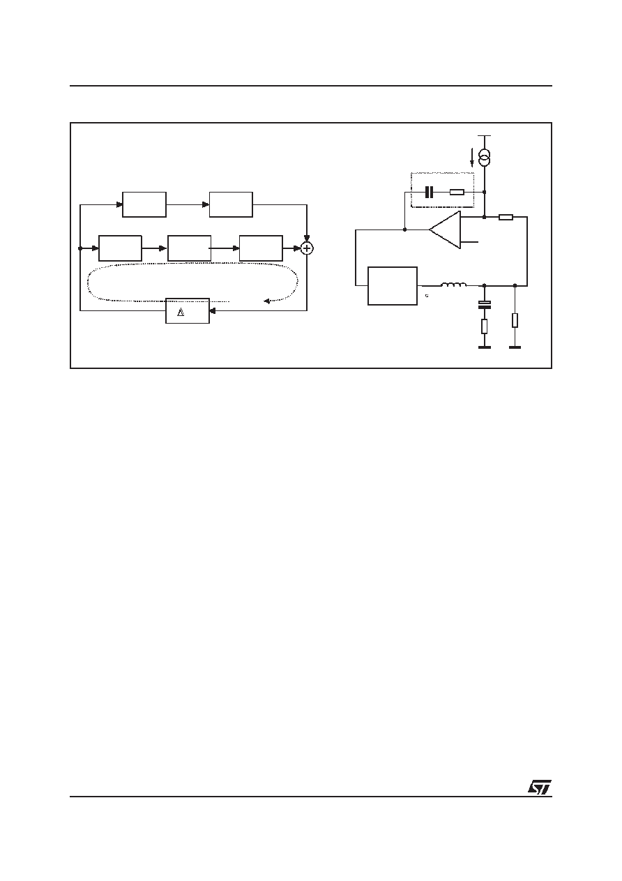
Figure 11. Control Loop Scheme
Average Current Mode Compensation Network Design
The average current mode control loop is reported in figure 11. The current information IFB sourced by the FB
pin flows into RFB implementing the dependence of the output voltage from the read current.
Two different loops are present and precisely a current loop internal to a voltage loop. The current gain (Ac) and
voltage gain (Av) present in the above figure are defined by the following relationships:
The current loop gain may now be expressed by the following equation:
Where
Vosc has a typical value of 2V and ZF(s) is the impedance of the series RF-CF. The current loop gain
is designed to obtain a high DC gain to minimize static error and cross the 0dB axes with a constant -20dB/dec
slope with a crossover frequency
ωTI. Neglecting the effect of ZF(s), the transfer function has one zero and two
poles. Both the poles are fixed once the output filter is designed and also the zero (
ωOUT=1/ROUTCOUT) is fixed
by the maximum current deliverable by the converter. To obtain the desired shape an RF-CF series network is
considered for the ZF(s) implementation. A zero at ωF=1/RFCF is then introduced together with an integrator.
This integrator minimizes the static error while placing the zero in correspondence with the L-C resonance a
simple -20dB/dec shape of the gain is assured (See Figure 12).
Rout
Cout
ESR
L
RFB
RF
CF
REF
PWM
IFB
Av
-ZF/RFB
Ac
Rs/Rg
-ZF
1/
Vosc
VCOMP
VOUT
d
VIN
VCOMP
VOUT
d
IFB
IOUT
ZF
GLOOPI
Av s
()
V
OU T
d
---------------
....
{}
V
IN
1s
+
ESR C
OUT
S
2
C
OUT
L
2
---
sESR C
OUT
L
2R
OUT
-----------------------
+
1
+
+
-----------------------------------------------------------------------------------------------------------------------------
==
=
Ac s
()
I
OUT
d
------------
....
{}
V
IN
R
OU T
---------------
1s
+
ESR C
OUT
S
2
C
OUT
L
2
---
sESR C
OUT
L
2R
OUT
-----------------------
+
1
+
+
-----------------------------------------------------------------------------------------------------------------------------
===
G
LOOPI s
()
Ac s
() Rs Z
F s
()
Rg
Vosc
-----------------------------------------------
V
IN
R
OUT
---------------
1s
+
ESR C
OUT
S
2
C
OUT
L
2
---
s
ESR C
OUT
L
2R
OUT
-----------------------
+
1
+
+
------------------------------------------------------------------------------------------------------------------------------
Rs
Rg
--------
Z
F s
()
Vosc
------------------
–
==
相关PDF资料 |
PDF描述 |
|---|---|
| L6918ADTR | SWITCHING CONTROLLER, 1200 kHz SWITCHING FREQ-MAX, PDSO28 |
| L6918AD | SWITCHING CONTROLLER, 1200 kHz SWITCHING FREQ-MAX, PDSO28 |
| L6919CD | SWITCHING CONTROLLER, 200 kHz SWITCHING FREQ-MAX, PDSO28 |
| L6919E | SWITCHING CONTROLLER, PDSO28 |
| L6920DTR | 1.2 A SWITCHING REGULATOR, PDSO8 |
相关代理商/技术参数 |
参数描述 |
|---|---|
| L6917DTR | 制造商:未知厂家 制造商全称:未知厂家 功能描述:Analog IC |
| L6918 | 制造商:STMICROELECTRONICS 制造商全称:STMicroelectronics 功能描述:5 BIT PROGRAMMABLE MULTIPHASE CONTROLLER |
| L6918A | 制造商:STMICROELECTRONICS 制造商全称:STMicroelectronics 功能描述:5 BIT PROGRAMMABLE MULTIPHASE CONTROLLER |
| L6918AD | 功能描述:DC/DC 开关控制器 Prog Multi-Phase Cnt RoHS:否 制造商:Texas Instruments 输入电压:6 V to 100 V 开关频率: 输出电压:1.215 V to 80 V 输出电流:3.5 A 输出端数量:1 最大工作温度:+ 125 C 安装风格: 封装 / 箱体:CPAK |
| L6918ADTR | 功能描述:DC/DC 开关控制器 Prog Multi-Phase Cnt RoHS:否 制造商:Texas Instruments 输入电压:6 V to 100 V 开关频率: 输出电压:1.215 V to 80 V 输出电流:3.5 A 输出端数量:1 最大工作温度:+ 125 C 安装风格: 封装 / 箱体:CPAK |
发布紧急采购,3分钟左右您将得到回复。