- 您现在的位置:买卖IC网 > PDF目录43901 > L9484 (STMICROELECTRONICS) SWITCHING REGULATOR, 460 kHz SWITCHING FREQ-MAX, PSFM8 PDF资料下载
参数资料
| 型号: | L9484 |
| 厂商: | STMICROELECTRONICS |
| 元件分类: | 稳压器 |
| 英文描述: | SWITCHING REGULATOR, 460 kHz SWITCHING FREQ-MAX, PSFM8 |
| 文件页数: | 9/11页 |
| 文件大小: | 162K |
| 代理商: | L9484 |
L9484
7/11
2.4
Diagnostic
2.5
Fault indication
2.6
Regulation features
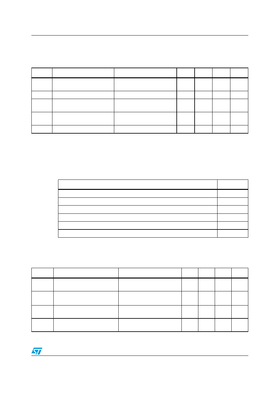
Table 6.
Diagnostic
(Tcase = -35°C to +150°C unless otherwise specified)
Symbol
Parameter
Conditions
Min.
Typ.
Max.
Units
VOV
Over-voltage
VSP + 1
VSP +
1.3
VSP + 2
V
VL-SAT
Lamp ON saturation voltage
IL = 0.5A (sinked by ASVR)
>VL-ACT
1.33
1.45
V
VL-SAT-BO Lamp ON voltage
(1)
IL < 0.5A, VGO = open; Tcase = -
35
°C to 85°C
3.8
5
V
VL-RLY
Lamp OFF (relay drive)
saturation voltage (vs. B+)
IL = 750mA (sourced by
ASVR)(2) Tcase < 125C
1.85
V
TDELAY
Fault indication delay time
Delay before lamp ON
0.9
1.1
1.3
s
1.
This condition can happen when the connection between the battery and VGO or the output terminal of the generator is
broken. The 1.1 second delay is not required, and current is sinked by ASVR.
2.
When no fault is detected the Lamp terminal is pulled up by ASVR.
Table 7.
Fault indication table
Conditions
TDelay?
Initial KEY-ON Bulb and wiring check (lamp ON for 1 sec
± 15% after initial KEY-ON)
No
VGO > VOV
Yes
VP < VP-F AND VGO < VSP
Yes
FP < FP-TR @ VP-TR
Yes
No connection between battery and VGO
No
At start: lamp ON until FP>FP-IR AND VP>VP-F. i.e. until VP reaches 8V.
No
Table 8.
Regulation features
Symbol
Parameter
Conditions
Min.
Typ.
Max.
Unit
VL-PD
L terminal regulator activate
threshold
VGO=12.6V
0.8
1
1.15
V
IL-PD
L terminal pull down current
VL = VL-ACT
VGO=12.6V
0.09
0.78
mA
VP-IR
Initiate regulation phase voltage
threshold
Regulator activated
1.1
1.3
1.5
V
VP-TR
Terminate regulation phase
voltage threshold
Regulator activated
1.1
1.3
1.5
V
相关PDF资料 |
PDF描述 |
|---|---|
| L9903 | BRUSH DC MOTOR CONTROLLER, PDSO20 |
| L9903TR | BRUSH DC MOTOR CONTROLLER, PDSO20 |
| L9911B | BRUSH DC MOTOR CONTROLLER, SFM8 |
| L9911A | BRUSH DC MOTOR CONTROLLER, SFM8 |
| L9911 | BRUSH DC MOTOR CONTROLLER, SFM8 |
相关代理商/技术参数 |
参数描述 |
|---|---|
| L9500A | 制造商:AGERE 制造商全称:AGERE 功能描述:High-Voltage Ringing SLIC for VolP Applications |
| L9503 | 制造商:Leviton Manufacturing Co 功能描述: |
| L9505 | 制造商:Leviton Manufacturing Co 功能描述: |
| L9508 | 制造商:Leviton Manufacturing Co 功能描述: |
| L9509 | 制造商:Leviton Manufacturing Co 功能描述: |
发布紧急采购,3分钟左右您将得到回复。