- 您现在的位置:买卖IC网 > PDF目录30714 > LA1235 FM, AUDIO DEMODULATOR, PDIP16 PDF资料下载
参数资料
| 型号: | LA1235 |
| 元件分类: | 接收器 |
| 英文描述: | FM, AUDIO DEMODULATOR, PDIP16 |
| 封装: | DIP-16 |
| 文件页数: | 8/13页 |
| 文件大小: | 289K |
| 代理商: | LA1235 |
LA1235
No. 873- 4/13
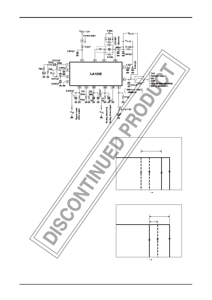
Test Circuit
Setting of muting sensitivity, hysteresis width (Refer
to the equivalent circuit block diagram and application
circuit). Muting sensitivity and hysteresis width are set
arbitarily by varying resistors R204 and R205
connected to pins 15 and 16, respectively. Muting
sensitivity is set by varying R204 ; and if R204 is made
larger, muting sensitivity will shift to the weak signal
side. Hysteresis width is set by varying R205 ; and if
R205 is made larger, hysteresis width will narrow.
Next, how to set muting sensitivity is concretely
described as follows. In case of using R204 =
50k
Ω (semifixed resistor) and R205 = 56kΩ, the upper
limit of current I16, 50μA, delivered from the signal
meter driver at which muting is turned ON is obtained
from the first quadrant of Table for muting adjustable
lower limit calculation. Muting is turned ON at
I16 ≤ 50μA. If I16 ≤ 50μA, muting is already turned
ON at a point of input being stronger than the setting
input and it is impossible to adjust muting at the
setting input. Therefore, I16 > 50μA is required at the
setting input. The input at which a sample with a small
I16 output meets 50μA is obtained as VIN = 47dBμ.
This input is the maximum value of muting sensitivity,
that is to say, the lower limit at with muting can be set.
The data for sample with a Small I16 shown in this
Table is colose to the minimum value, but since
samples with values less than this minimum value may
occur, a margin of some dB
μ must be allowed. From
the above, the minimum value for muting setting
(muting ON input) becomes 50dB
μ for R204
(semifixed resistor) = 50k
Ω and R205 = 56kΩ.
Muting sensitivity setting by means of R204
Input signal
Larger
Large R204
Small R204
Muting
v
oltage
Hysteresis width setting by means of R205
Input signal
Larger
Large R205
Muting
v
oltage
Small R205
相关PDF资料 |
PDF描述 |
|---|---|
| LA1245 | AUDIO SINGLE CHIP RECEIVER, PDIP20 |
| LA1247 | AM, AUDIO SINGLE CHIP RECEIVER, PDIP20 |
| LA1260 | AM/FM, AUDIO SINGLE CHIP RECEIVER, PDIP16 |
| LA1265 | AM/FM, AUDIO SINGLE CHIP RECEIVER, PDIP22 |
| LA1266 | AM/FM, AUDIO SINGLE CHIP RECEIVER, PDIP24 |
相关代理商/技术参数 |
参数描述 |
|---|---|
| LA1235MC-AH | 制造商:ON Semiconductor 功能描述:HOME TUNER IC - Tape and Reel 制造商:ON Semiconductor 功能描述:REEL / HOME TUNER IC |
| LA1240 | 制造商:SANYO 制造商全称:Sanyo Semicon Device 功能描述:LA1240 |
| LA1245 | 制造商:未知厂家 制造商全称:未知厂家 功能描述:AM 电子调谐器 |
| LA1247 | 制造商:SANYO 制造商全称:Sanyo Semicon Device 功能描述:AM ELECTRONIC TUNER |
| LA12540 | 制造商:LIGITEK 制造商全称:LIGITEK electronics co., ltd. 功能描述:ROUND TYPE LED LAMPS |
发布紧急采购,3分钟左右您将得到回复。