- 您现在的位置:买卖IC网 > PDF目录30720 > LA7106M 3 CHANNEL, VIDEO AMPLIFIER, PDSO16 PDF资料下载
参数资料
| 型号: | LA7106M |
| 元件分类: | 音频/视频放大 |
| 英文描述: | 3 CHANNEL, VIDEO AMPLIFIER, PDSO16 |
| 封装: | 0.225 INCH, MFP-16 |
| 文件页数: | 5/5页 |
| 文件大小: | 108K |
| 代理商: | LA7106M |
LA1845N
No.7185-5/9
Continued from preceding page.
Pin No.
Pin function
Pin voltage (V)
Pin description
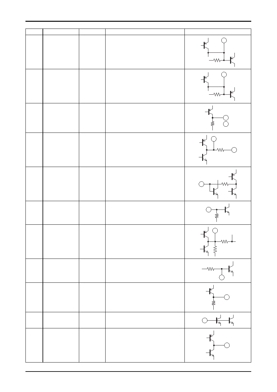
Equivalent circuit
11
Phase comparator
low-pass filter
(AM/FM switching)
VCC-1.0
The device operates in AM mode when a current of
over 200
μA flows from pin.12.
Limit values for the resistor :
2.7k
Ω (When VCC = 7V)
3.9k
Ω (8V)
11
12
Pilot detector
low-pass filter
(Forced mono)
(VCO stop)
VCC-1.0
The device is forced to monaural when a current of
over 50
μA flows from this pin.
The VCO is stopped when a current of over 200
μA
flows from this pin.
The limit values for the resistor are the same as
those for pin 11.
12
13
14
L outputs
R outputs
3.2
Output impedance ro = 3.3kΩ
13
( 14 )
15
Pilot canceler output
Vreg
15
3
16
Decoder input
Vreg
Inverting input pin
RNF = 20k
Ω
RNF
16
17
PLL input
Vreg
Input impedance ri = 20kΩ
17
18
FM demodulator
output
Vreg + 0.7
Output impedance ro = 2.3kΩ
The channel separation can be adjusted with an
external capacitor connected between this pin and
ground.
18
19
AM detector output
0 (FM)
1.5 (AM)
Output impedance ro = 10kΩ
100V
19
20
S meter,
AM AGC
0.2 (FM)
0.9 (AM)
The resistance of the built-in resistor R is 13.9k
Ω
The SD responce during seek operation is
determined with the external capacitor connected to
this pin.
20
R
21
AM RF input
Vreg
Must be used at the same potential as pin 22.
21
22
AFC
Vreg
The FM SD bandwidth can be adjusted with the
external resistor connected between this pin and
pin 3 (Vreg).
22
Continued on next page.
相关PDF资料 |
PDF描述 |
|---|---|
| LA71076SM | SPECIALTY CONSUMER CIRCUIT, PQFP100 |
| LA71076SM | SPECIALTY CONSUMER CIRCUIT, PQFP100 |
| LA7108M | 3 CHANNEL, VIDEO AMPLIFIER, PDSO16 |
| LA7109 | 6 CHANNEL, VIDEO AMPLIFIER, PDSO36 |
| LA7116 | SPECIALTY CONSUMER CIRCUIT, PDIP24 |
相关代理商/技术参数 |
参数描述 |
|---|---|
| LA7108M-TLM-E | 制造商:Sony Semiconductor Solutions Division 功能描述: |
| LA7110 | 制造商:SANYO 制造商全称:Sanyo Semicon Device 功能描述:VTR TAPE END DETECTOR |
| LA7110M | 制造商:未知厂家 制造商全称:未知厂家 功能描述:Analog IC |
| LA7112M | 制造商:未知厂家 制造商全称:未知厂家 功能描述:Analog IC |
| LA7116 | 制造商:SANYO 制造商全称:Sanyo Semicon Device 功能描述:VCR Servo Interface |
发布紧急采购,3分钟左右您将得到回复。