- 您现在的位置:买卖IC网 > PDF目录30725 > LA7688B AM/FM, AUDIO/VIDEO DEMODULATOR, PDIP52 PDF资料下载
参数资料
| 型号: | LA7688B |
| 元件分类: | 接收器 |
| 英文描述: | AM/FM, AUDIO/VIDEO DEMODULATOR, PDIP52 |
| 封装: | 0.600 INCH, DIP-52 |
| 文件页数: | 9/20页 |
| 文件大小: | 316K |
| 代理商: | LA7688B |
LA7688B
No.0077-17/20
Deflection block Input signals and test conditions
Set up the following conditions unless otherwise specified for each test item.
(VIF, SIF blocks : No signal)
1. EXT VIDEO IN :
Horizontal vertical composite signal (1Vp-p, same as for video block, chroma block)
(I-14A)
Horizontal sync signal only (0.5Vp-p, pulse width 4.7s)
Open
2. SW conditions : All SW's turned off unless otherwise specified
3. VCC, ICC conditions : VCC = 7.8V, ICC = 12mA
Parameter
Symbol
Test
point
Input
signal
Test method
SW20
SW25
[Deflection block]
TV free
50
Z-20B
I-14A :
No signal
With Z-21 connected to GND, measure the vertical
output period at Z-20B and calculate the ratio to the
horizontal period.
OFF
B
Vertical free-running period
TV free
60
Z-20B
I-14A :
No signal
With 7.8V applied to Z-21, measure the vertical
output period and calculate the ratio to the
horizontal period.
OFF
B
TV max50
Z-20B
I-14A :
Horizontal
sync signal
With Z-21 connected to GND, measure the vertical
output period at Z-20B and calculate the ratio to the
horizontal period.
OFF
B
Vertical sync maximum
period
TV max60
Z-20B
I-14A :
Horizontal
sync signal
With 7.8V applied to Z-21, measure the vertical
output period and calculate the ratio to the
horizontal period.
OFF
B
TV min50
Z-20B
O-25
I-14A :
Horizontal
sync signal
Apply 8.5V and 0V to Z-27B and Z-21,
respectively. Turn off SW20 and make adjustments
so that the resistance between O-20 and GND
becomes 4.7k
and then turn on SW20.
Calculate the ratio between the vertical output
period at Z-20B and the horizontal output period at
O-25.
OFF
↓
ON
B
Vertical sync minimum
period
TV min60
Z-20B
O-25
I-14A :
Horizontal
sync signal
Apply 8.5V and 7.8V to Z-27B and Z-21,
respectively.
Make measurements in the same manner as for
TV min 50.
OFF
↓
ON
B
Vertical blanking pulse peak
value
VHVBL
O-32
I-14A :
Horizontal
vertical sync
signal
Measure the vertical blanking pulse peak value in
the video output at O-32.
(GND is assumed to be 0V.)
OFF
B
PW BLK50
O-32
I-14A :
Horizontal
sync signal
With Z-21 connected to GND, measure the vertical
blanking pulse width in the video output at O-32
and calculate the ratio to the horizontal period.
OFF
B
Vertical blanking pulse
width
PW BLK60
O-32
I-14A :
Horizontal
sync signal
With 7.8V applied to Z-21, measure the vertical
blanking pulse width in the video output at O-32
and calculate the ratio to the horizontal period.
OFF
B
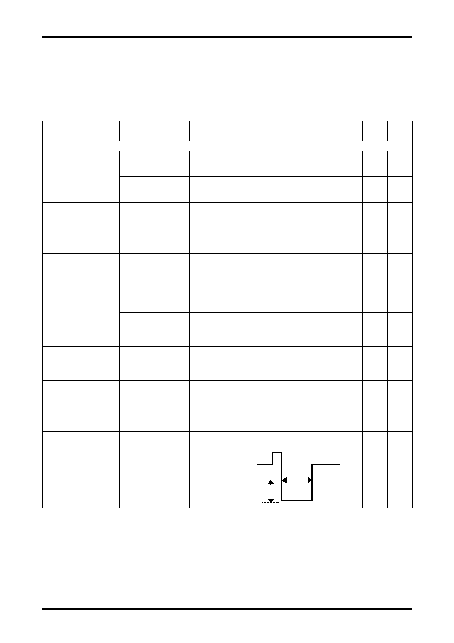
Vertical output pulse width
PWVOUT
Z-20B
I-14A :
Horizontal
vertical sync
signal
Measure the vertical output width at Z-20B and
calculate the ratio to the horizontal period.
OFF
B
Continued on next page.
0V
PWOUT
3V
相关PDF资料 |
PDF描述 |
|---|---|
| LA7688 | AM/FM, AUDIO/VIDEO DEMODULATOR, PDIP52 |
| LA76919M | SPECIALTY CONSUMER CIRCUIT, PQFP80 |
| LA76931K | SPECIALTY CONSUMER CIRCUIT, PDIP64 |
| LA76931K | SPECIALTY CONSUMER CIRCUIT, PDIP64 |
| LA76938Y | SPECIALTY CONSUMER CIRCUIT, PDIP64 |
相关代理商/技术参数 |
参数描述 |
|---|---|
| LA76922M | 制造商:SANYO 制造商全称:Sanyo Semicon Device 功能描述:Signal-Processing IC with Integrated Microcontroller |
| LA76930 | 制造商:SANYO 制造商全称:Sanyo Semicon Device 功能描述:LA76930 |
| LA76931J7FB-E | 制造商:ON Semiconductor 功能描述:SIGNAL PROCESSING FOR CRT - Ammo Pack 制造商:ON Semiconductor 功能描述:FNFLD / SIGNAL PROCESSING FOR CRT |
| LA76931K7N5BD3-E | 制造商:Sony Semiconductor Solutions Division 功能描述: |
| LA76936Y7FB-E | 制造商:ON Semiconductor 功能描述:SIGNAL PROCESSING FOR CRT - Ammo Pack |
发布紧急采购,3分钟左右您将得到回复。